



2. Turn the steering wheel until it locks.
3. Using a suitable tool, lift the upper steering column trim panel in the direction of the arrows (arrows A), then remove the cover in the direction of arrow B.
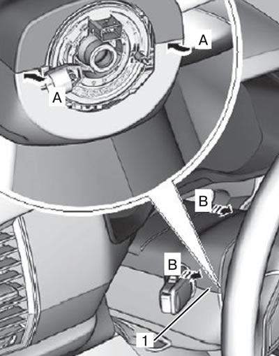
4. If necessary, remove the steering wheel (for more details, see the relevant section in the chapter "Steering").
Caution: Do not connect electrical measuring instruments to the airbag terminals. It is possible that the pyropatron may spontaneously trigger, resulting in serious injuries.
Caution: To prevent accidental airbag deployment, do not use any storage devices. Failure to follow this instruction may result in serious injury or death.
Caution: Before starting any work, turn off the ignition and disconnect the negative battery terminal, then wait at least 3 minutes.
Caution: Always work from the side of the airbag module; avoid working in front of the module.
Caution: After removal, always store the driver's airbag module with the housing facing down and the decorative cover facing up. Never store the airbag module with the cover facing down. Failure to follow this instruction may result in serious injury.
Note: Repair of passive safety system components is not provided. In case of failure, the damaged element is replaced as an assembly.
Attention:
- Do not expose the airbag module to temperatures exceeding 90 degrees Celsius.
- Prevent oil products, solvents and/or water from coming into contact with the airbag module.
Caution: Always replace the airbag module mounting bolts after disassembly and assembly.
Attention:
- Use extreme caution during installation to avoid damaging the airbag module wiring harness.
- Before installing and tightening the mounting bolts, check and ensure that the holes in the module and the steering wheel are aligned, otherwise the airbag module may be damaged.
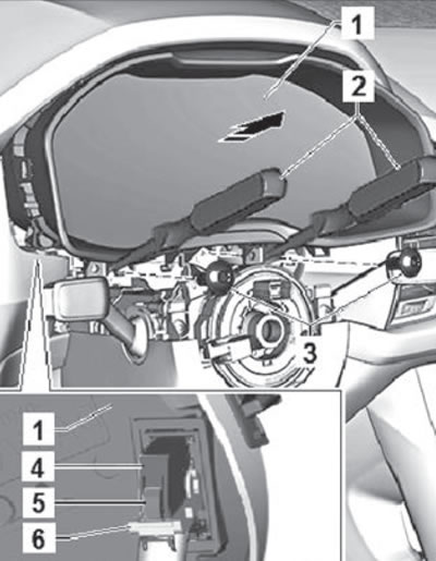
5. Unscrew the mounting screws (3) shown in the figure below.
Attention:
- Next, operations are performed that may damage the instrument panel. Be extremely careful!
- Do not apply force to the plate when removing the instrument cluster.
6. Insert the special tool T10389 or 3370 (2) into the instrument panel support tabs, then detach the panel (1) one by one from all fasteners, holding it (arrows).
7. Press the lock (5) and disconnect the wiring harness connector (4) by tilting the clamp (6) as shown in the figure below.
8. Remove the instrument panel assembly.
9. Installation is carried out in the reverse order of removal.