
Scheme of strengthening the contact in the connector housing
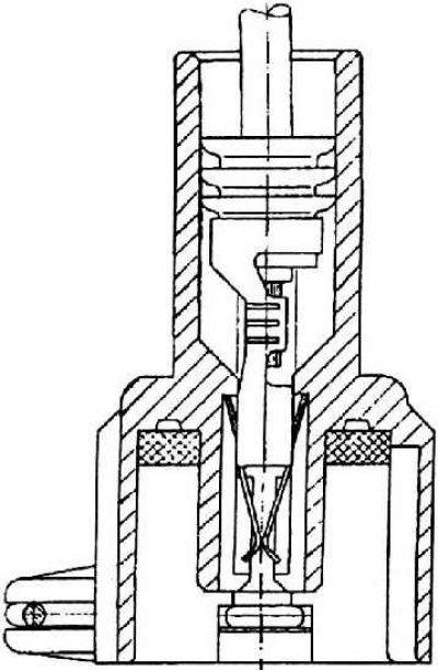
The contact is fixed in the connector housing without secondary fixation with an additional cartridge.
Contact
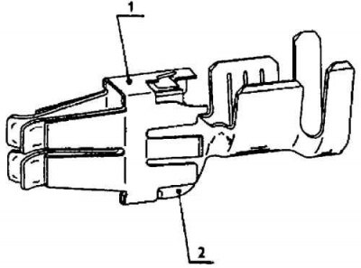
1 - fixing part (stainless steel);
2 - contact body (tinned bronze)
Loop connection diagram
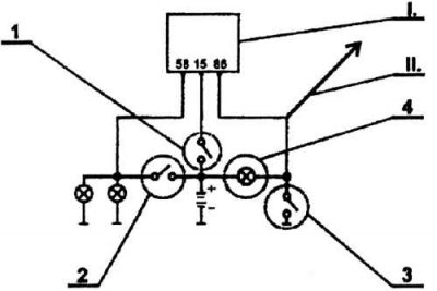
1 - ignition switch; 2 - headlight switch; 3 - door switch; 4 - interior lighting; I - alternative; II - alternative
Wiring designed for rated voltage 12 V (operating voltage 14 V) single wire system. This means that one wire - the minus pole - is replaced by a metal frame and metal parts of the car. The wiring is FLRY type copper braided wire. Wire cross section from 0.35 to 35 mm. Hardened plastic wire insulation in different colors. The color is determined according to the function of the wire and is specified by the standard (DIN).
The wires are bundled and wrapped with adhesive tape. In the cab of the car, the bundles are wrapped exclusively with textile tape, in the engine compartment in some parts with textile tape, in other places with PVC tape. One beam passes through the entire car from the engine compartment to the rear lights. The next two beams are in the engine compartment, four beams lead to the side doors and two or even three (depending on vehicle specification) to the rear flap. Along the way, the bundles are attached with plastic clamps, which are either inserted with spikes into punched holes in the sheets, or thrown over bolts welded to the body. In two places - the engine compartment and along the central tube under the dashboard - the beams were passed through dissected figured plastic channels. Interestingly, washer tubes are also a component of cable bundles. Wiring routes are factory-set and cannot be further modified. This position satisfies all instructions and its implementation is supported.
This layout concept, firstly, increases reliability, and secondly, it allows wiring from separate simple bundles with different options (when installing special equipment or a different vehicle version - LX, GLX, SLX), as well as in the case of further expansion or new functions, so that the entire wiring system does not need to be redesigned or changed on the finished car. Cable wiring includes all connectors, terminal blocks, fuse panel with small and large fuses, relay panel and switch box as mounting units.
The connectors have a reliable contact with the wires, then the fixation of the contact in the terminal block housing and, in addition, further mechanical secondary fixation with an additional cartridge. The contact is fixed by two elastic tongues. After inserting the terminal blocks, the housings are mechanically fixed from falling out. The contact material is binary. The contact part is made of tinned bronze, the fixing part is made of stainless steel. Connectors of critical connections and connections in the engine compartment are gold-plated. On fig. Scheme of strengthening the contact in the connector housing, fig. The contact schematically shows the fixation of the contact in the body of the connector and the contact itself. This solution is of high quality both from a constructive point of view and from a production point of view and guarantees a defect-free operation of the electrical system. Completed bundles of wires after production are 100% checked and controlled by a tester for performance.
There is a great variety of types and combinations of cable wiring. They differ according to the type of vehicle, its version, modification, equipment, etc. Connection diagrams are available from the ŠKODA Service Department, which should be contacted in the event of a malfunction in the electrical system.
In all vehicles not equipped with SPDP (abbreviation for vehicles intended for a country in which driving with headlights permanently on is prescribed - daytime running lights), the instrument panel is equipped with an AKIN circuit - an indicator of the included headlights. The AKIN circuit indicates with an acoustic signal that the headlights are switched on if the driver's doors are open and the ignition is switched off at the same time. The connection diagram of the AKIN circuit is shown in fig. Circuit connection diagram. Connection according to the first option refers to cars in the LX version, i.e. without central locking.
Connection according to the second option is used in cars with central locking.
Wire N 86 is connected to the central lock control unit (standard version GLX and SLX).
The vehicle is also equipped with an X-contact or unloader relay. It is located on the relay panel (position 2). Relay with function X provides automatic shutdown of all consumers except side lights during engine start. This is in order to unload the battery with a large selection of current by the starter.
A further increase in consumer comfort is the automatic activation of the sleeper, which controls the interior lighting. If the door is left open, it turns off the interior lighting after 30 minutes. If the lighting is on with the doors closed and is not turned off within 60 minutes, it will turn off automatically. Thanks to this, the battery is not discharged due to the left lighting.