



Assembly diagram of the hydraulic system 02J
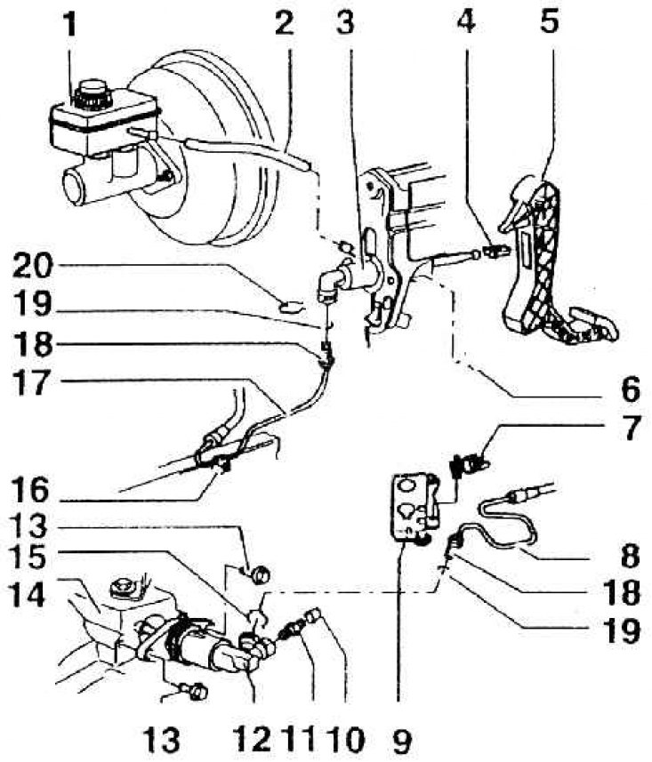
1 – brake fluid reservoir; 2 – supplementary hose; 3 – clutch master cylinder; 4 – fastening (replace only when clutch master cylinder is removed); 5 – clutch pedal; 6 – self-locking nut, 25 Nm (replace every time); 7 – holder (secure to the counter support, pos. 9); 8 – hose line and pipeline (for left-hand and right-hand drive vehicles, determine according to the parts catalog); 9 – counter support; 10 – dust cap; 11 – air valve; 12 – clutch booster slave cylinder (can be removed without disassembling the gearshift mechanism parts); 13 – flange bolt, 25 Nm; 14 – gearbox; 15 – locking clamp; 16 – pressure clamp (attached to the body); 17 – hose line and pipeline (for left-hand and right-hand drive vehicles, determine according to the parts catalog); 18 – connecting the pipe; 19 – O-ring of circular cross-section (replace every time); 20 – safety bracket