
Assembly diagram of the pedal mechanism
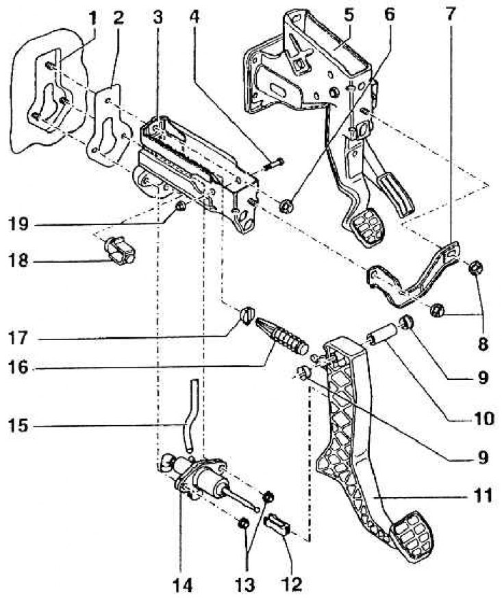
1 - fastening / front wall (for clutch master cylinder and bearing bracket); 2 - seal (replace every time); 3 - bearing bracket; 4 - a screw with a six-sided head; 5 – the pedal mechanism of an accelerator/brake; 6 - self-locking nut, 25 Nm (replace every time); 7 - connecting pad; 8 - self-locking nut, 20 Nm (replace every time); 9 - spacer bushings; 10 - bearing sleeve; 11 - clutch pedal; 12 - fastening; 13 - self-locking nut, 25 Nm (replace every time); 14 - clutch master cylinder; 15 - supplementary hose; 16 - spring; 17 - support / spring (insert into pedal bracket, replace each time); 18 - pedal stop; 19 - self-locking nut, 25 Nm (replace every time)
Required special tools, gauges and fixtures: Polyurea grease G052 142 A2.
Attention! Disconnect the battery cable for a short to "mass".
Attention! For vehicles with a radio equipped with an anti-theft jamming code, identify the code and mark it.
Attention! All bearing surfaces and contact surfaces must be lubricated with polyurea grease G 052 142 A2.
Attention! Before working on the pedal mechanism, the lower cover on the driver's side must be removed.