
Assembly diagram of the hydraulic system 02K
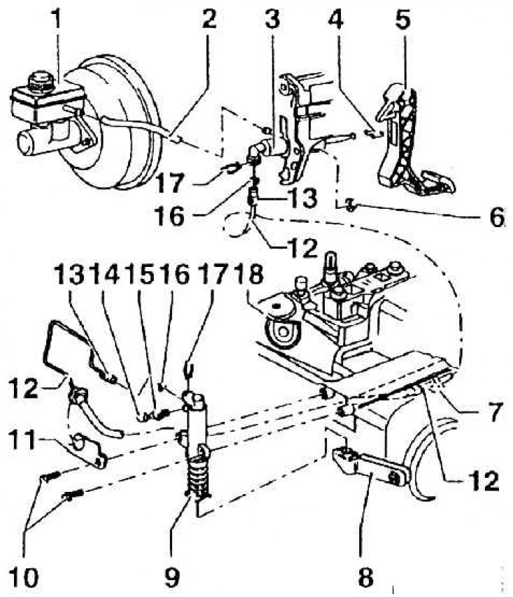
1 – a tank for a cooling liquid; 2 – additional hose; 3 – the main cylinder of coupling; 4 - mount (only replace when the clutch master cylinder has been removed); 5 - clutch pedal; 6 - self-locking nut, 25 Nm (replace every time); 7 - clamping clamp (fasten to body); 8 - clutch release lever; 9 – working cylinder of the amplifier of a drive of coupling (for disassembly purposes, loosen the shoulder bolts, item 10, and remove the locking clips, item 17); 10 - bolt with shoulder, 25 Nm; 11 - holder; 12 - hose line and pipeline (for vehicles with left-hand drive and right-hand drive, determine according to the spare parts catalog); 13 - union nut; 14 - dust cap; 15 - air valve; 16 - O-ring (replace every time); 17 - locking clip; 18 - gearbox