
Note: Empty the fuel tank.
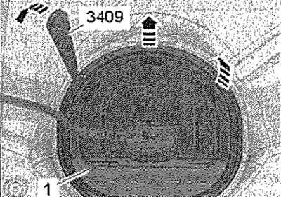
Move the front seats all the way forward. Switch off the ignition and remove the ignition key from the lock. Remove rear seat. Unlock cover clips -1- with wedge -3409- -arrows-.
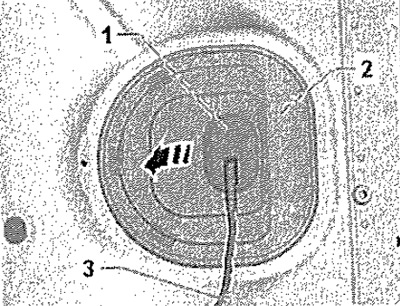
Remove sealing sleeve -1- from cover -2- towards bottom. Pull back cover -2- along wiring harness -3-.
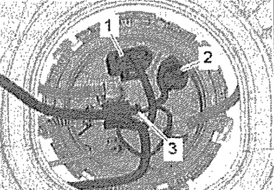
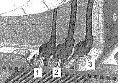
Disconnect the connectors -1, 2- from the connecting flange by releasing the connector locks. If present, unplug connector -3- for auxiliary heater metering pump -V54-, unlocking connector.
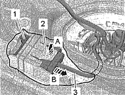
Press locking tab -2- upwards -arrow A- by grasping between underbody and fuel tank with finger. At the same time, carefully remove the fuel pump control unit -J538- -pos. 1- along the wiring harness -3- from the bracket -arrow B-. Remove fuel pump control unit -J538- between fuel tank and support. Clean the area around the filler neck. Unscrew the filler cap.
Note: Cover the filler opening with a clean cloth to prevent dirt from entering.
Remove the filler cap. Remove the rear right wheel. Remove the rear right fender liner.
Vehicles with torsion beam suspension
Remove the brake caliper for the right rear wheel and set aside. Disconnect the rear right wheel ABS sensor connector and remove the wire from the mountings on the rear axle.
All
Remove screws -1, 2- for filler neck. Remove the rear muffler.
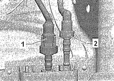
Disconnect fuel supply line -1- and fuel return line -2-. Unlock and disconnect the quick coupler.
Vehicles with auxiliary heater
Disconnect fuel line -1- to auxiliary heater. Unlock and disconnect the quick coupler.
Vehicles with multi-link suspension
Mark the direction of travel of the vehicle on the yoke. Remove screw -4-. Remove the hanger for the exhaust system. Remove screw -2- and remove clamp.
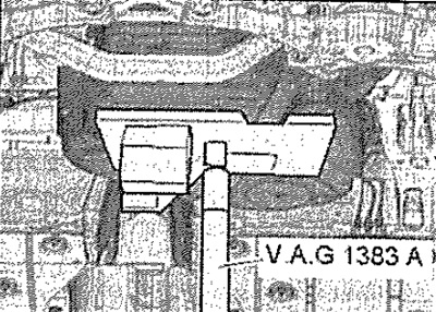
Place the engine and transmission jack -VAG 1383 A- under the vehicle to prevent it from hanging out and support the fuel tank on it as shown in the figure.
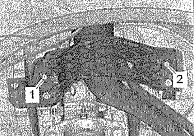
Remove screws -1- and -3-.
Note: For clarity, the fuel tank is shown in the illustration without the engine and gearbox jack -VAG 1383A-. The assistance of a 2nd mechanic is required to remove the fuel tank.
Lower fuel tank with engine and gearbox jack -VAG 1383 A-. Tilt the fuel tank to the side appropriately and lower it. Route the filler plug between the rear suspension and the body.
Vehicles with torsion beam suspension
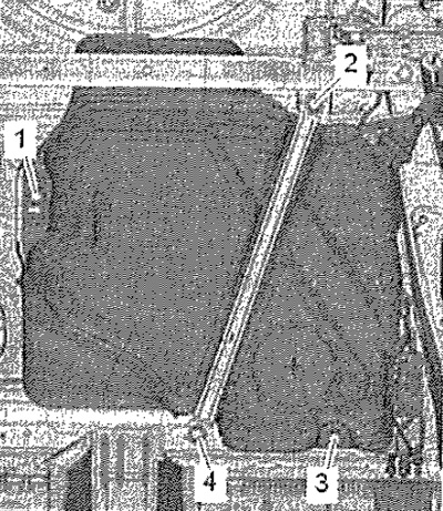
Mark the direction of travel of the vehicle on the yoke. Remove screw -5-. Remove hanger for exhaust system -arrow-. Release screws -3- and remove clamp -7-.
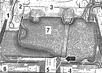
Place the engine and transmission jack -VAG 1383 A- under the vehicle to prevent it from hanging out and support the fuel tank -1- on it as shown in the figure.
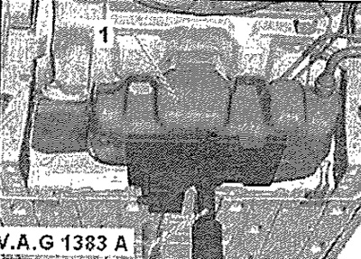
Remove screws -2-, -4- and -6-. Lower fuel tank with engine and gearbox jack -VAG 1383 A-. Tilt the fuel tank to the side appropriately and lower it. Route the filler plug between the rear suspension and the body.
Installation
Note: Replace sealing rings. When connecting electrical connectors, pay attention to the reliability of the lock.
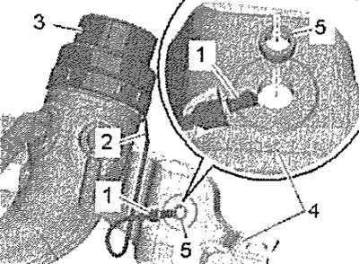
Check the installation position of the end of the tank exhaust ventilation line. Check ground wire connector for corrosion, clean if necessary. Check the reliability of the fastening of the connectors. The connector -2- must be firmly seated on the metal ring -3-. The contact tab -1- must be attached to the fuel tank -4- and secured with a spacer sleeve -5-.
Attention! Electrostatic discharge hazard. After installation, use an ohmmeter to check the electrical connection between the metal ring on the filler neck and the cleaned metal surface on the body. Nominal resistance value: approximately 0 ohm.
Check whether the fuel lines are clipped to the fuel tank. Use engine and gearbox jack -VAG 1383 A- to place the fuel tank with the clamps under the bottom of the vehicle. When placing the fuel tank, make sure that the filler neck fits correctly into the hole on the body.
Note: The new clamp screws are longer, observe the part number.
Installation in reverse order.