
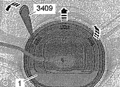
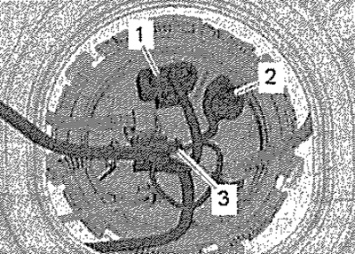
Disconnect connector -2- from the connecting flange, while releasing the connector locks. -Positions 1, 3- ignore.
Fuel gauge sender -G- fitted
Note: To achieve accurate resistance readings with "full fuel tank" if the sensor is installed, the fuel tank must be completely filled. After filling the fuel tank, drive at least 500 m more so that any air bubbles can escape from the fuel tank. Then add more fuel.
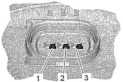
Connect a multimeter to measure resistance between terminals -B1- and -B2-: fuel tank empty: approx. 270 ohms, fuel tank full: approx. 70 ohms. Connect a multimeter to measure the resistance between contacts -B1- and -B3-: fuel tank empty: approx. 70 ohms, fuel tank full: approx. 270 ohms. Connect a multimeter to measure the resistance between contacts -B2- and -B3-: any sensor position: approx. 340 Ω.
Fuel gauge sender -G- removed
Note: When checking the resistance values "Fuel tank full"" or " Fuel tank empty" the fuel level sender -G- must be removed and the float lever swung up or down as far as it will go. The resistance of the removed fuel level sensor due to the extreme positions of the float lever has the following values.
Connect a multimeter to measure the resistance between contacts -B1- and -B2-: fuel tank empty: approx. 300 ohms, fuel tank full: approx. 52 ohms. Connect a multimeter to measure the resistance between contacts -B1- and -B3-: fuel tank empty: approx. 52 Ω, fuel tank full: approx. 300 Ω. Connect a multimeter to measure the resistance between contacts -B2- and -B3-: any sensor position: approx. 340 Ω.
The fuel level sender -G- is defective if the following facts are detected: large deviations of the measured values, value 0 Ω (short circuit), value ∞ Ohm (conductor break), no faults in electrical wires. Install fuel gauge sender -G-.