
Note.
- Necessary special devices, control and measuring devices, as well as auxiliary means:
- Remote control device such as (VAG 1348/ZA).
- Adapter (adapter). (V.A.G 1348/3-2).
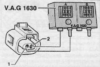
- digital potentiometer, (V.A.G 1630).
- Auxiliary measuring kit (VAG 1594 A, B nebo C).
- Measuring cylinders. (V.A.G 1602).
Note.
- Verify that the fuel pump relay is OK. Also make sure the fuel pump is working properly.
- The temperature of the fuel at which it is necessary to carry out tests should be 15-20°C, the fuel must comply with current standards.
1. Remove, if necessary, the decorative engine cover together with the air filter.
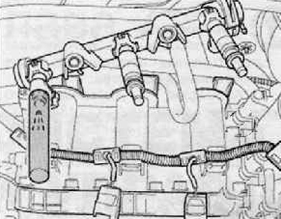
2. Remove the fuel rail together with the fuel injectors without disconnecting the fuel hoses from the rail (for details, see the relevant section in this chapter).
Checking the injection jet and tightness
3. Unplug electrical harness connector at coolant temperature sender -G62-.
4. Connect a digital potentiometer with an auxiliary wire to both pins of the wiring harness connector, set on the connected side to 15 kΩ.
5. Place a special container under one fuel injector, as shown in the figure below. Disconnect the wiring harness connectors from the other injectors.
6. Turn on the ignition and starter (assistance of a second mechanic is needed). The fuel injector should inject pulses.
7. Repeat the control for the remaining fuel injectors. Be sure to connect only the fuel injector under test.
8. Then check the tightness of the fuel injectors. If the nozzle is in normal condition, then within one minute there should not be more than two drops.
If the fuel leak is greater:
9. Turn off the ignition.
10. Replace defective fuel injector.
Checking the amount of injected fuel
Note. When checking the injected quantity, it is also necessary to check the jet of injected fuel. The latter should be the same for all fuel injectors.
11. Install the fuel injector to be tested in a special measuring cylinder.
12. Connect one fuel injector lead to the negative battery terminal.
13. Connect the second contact of the fuel injector to the remote control device.
14. Connect the clamp to the positive battery terminal.
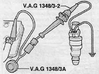
15. Using auxiliary cable with adapter -VAG 1348/3-2-, connect battery positive terminal and Ns 30 fuse holder. Fuel pump should run.
16. Press the button on the remote control for 30 seconds.
17. Repeat the control for the remaining fuel injectors. Always use a new graduated cylinder.
18. After arousal (activation) all fuel injectors, place all graduated cylinders on a horizontal base.
19. Disconnect the supply voltage to the fuel pump.
20. Compare the individual quantities of injected fuel.
Required value: 84...91 ml per fuel injector.
In the event that the measured value of one or more fuel injectors is outside the allowable required value:
Replace faulty fuel injectors.
1. Installation is made in reverse order to removal.
Replace O-rings on all fuel injectors and lubricate lightly with clean engine oil.
After installing the fuel injectors vertically and in the correct position in the fuel rail, fix them with locking clips.
After installing the fuel rail with fixed fuel injectors on the cylinder head, evenly tighten the rail mounting bolts with the application of the required tightening torque