



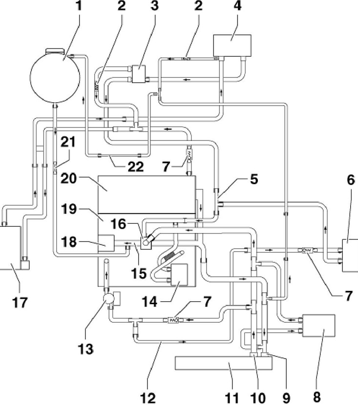
1.1 Cooling system circuit of a 3.6 l petrol engine (using the example of models with additional heating)
1 Expansion tank
2 Non-return valve, in the coolant hose, not visible from the outside
3 Valve N₂79 coolant supply cut-off for heater
4 Heater radiator, when replacing, replace the coolant
5 Coolant pipe, installed transversely at the rear
6 Oil cooler
7 Non-return valve
8 Additional radiator
9 Upper coolant hose
10 Lower coolant hose
11 Radiator
12 Coolant pipe, installed transversely in front
13 Coolant circulation pump "V55"
14 Oil cooler
15 Coolant pipe, with thermostat housing
16 Thermostat
17 Additional heater
18 Coolant pump
19 Cylinder block
20 Cylinder head
21 Throttle, in coolant hose, not visible from the outside
22 Coolant pipe at the rear
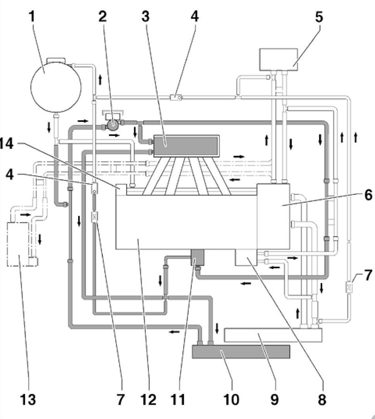
1.2 Cooling system circuit of 1.4 l petrol engine
Light outline of the engine cooling system coolant line
Dark outline of the intercooler coolant line
1 Expansion tank
2 Coolant circulation pump "V50"
3 Intercooler, in the intake manifold
4 Non-return valve, in the coolant hose, not visible from the outside
5 Heater radiator
6 Thermostat housing
7 Throttle, in the coolant hose, not visible from the outside
8 Oil cooler
9 Radiator
10 Additional radiator for intercooler
11 Turbocharger
12 Cylinder head and block
13 Additional heater, if available
14 Coolant pump
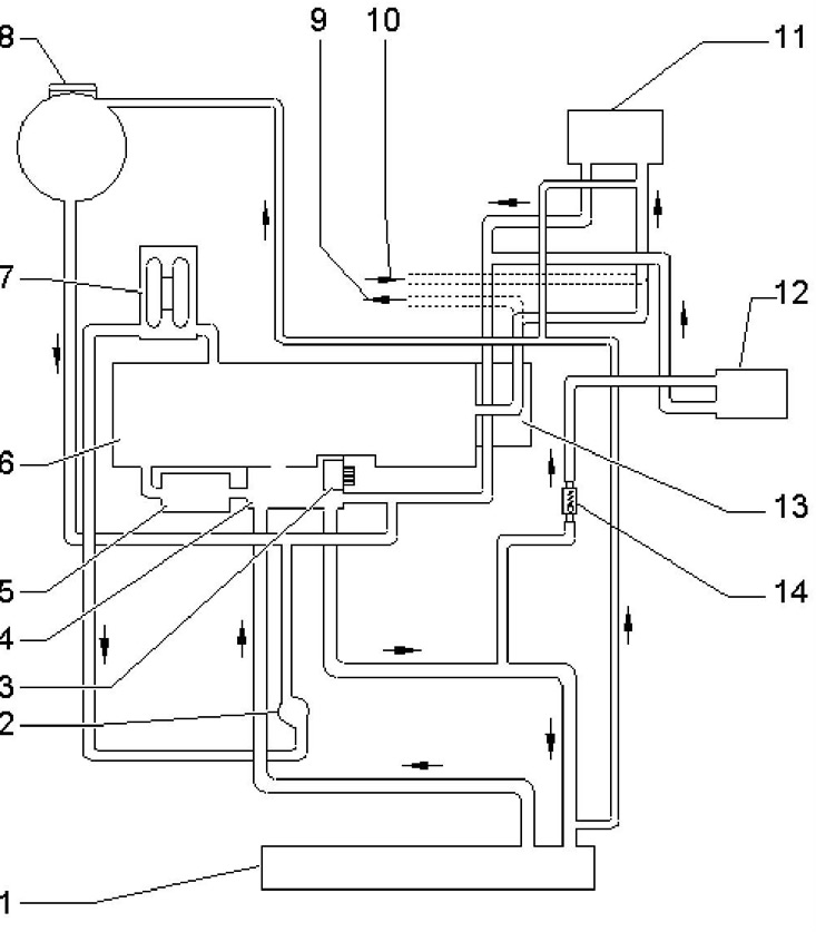
1.3 Cooling system circuit for 1.8 and 2.0 l petrol engines (using the example of models with DSG)
1 Radiator
2 Coolant circulation pump "V51"
3 Coolant pump
4 Thermostat
5 Oil cooler
6 Cylinder head and block
7 Turbocharger
8 Expansion tank
9 To additional heater
10 From additional heater
11 Heater radiator
12 DSG fluid radiator
13 Connecting coolant lines
14 Radiator regulating valve 12
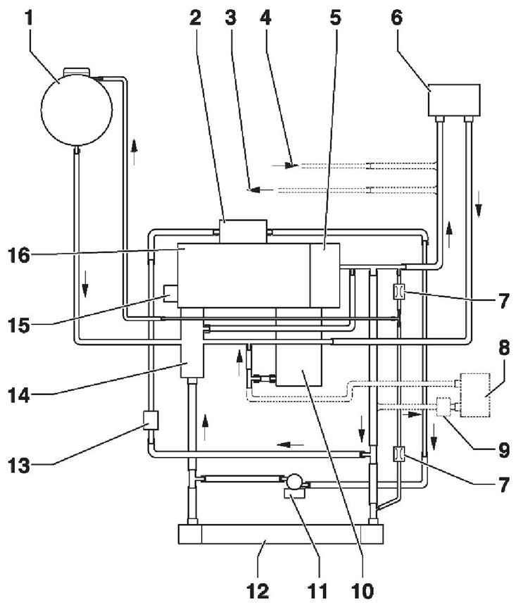
1.4 Cooling system circuit for 2.0 l diesel engines (CFFB, CFGB and CLJA)
1 Expansion tank
2 EGR radiator, after replacement, replace the coolant
3 To additional heater
4 From additional heater
5 Cylinder block, after replacement, replace the coolant
6 Heater radiator, after replacement, replace the coolant
7 Throttle, in the coolant hose, not visible from the outside
8 DSG fluid radiator
9 Regulator for radiator 8
10 Oil cooler, after replacement, replace the coolant
11 Coolant circulation pump No.2 "V178"
12 Radiator, after replacement, replace the coolant
13 Sensor "G83" coolant temperature at the radiator outlet
14 4/2-way valve, with thermostat
15 Coolant pump
16 Cylinder head, after replacement, replace the coolant
The engine cooling system operates according to the following algorithm. While the engine is not warmed up, the coolant (coolant) is pumped by the water pump only in the cylinder head and block, as well as in the heat exchanger of the interior heater. In this way, the engine warms up quickly. When the coolant temperature rises to a certain value (controlled by ECT sensor) the thermostat opens a large cooling circuit and the coolant circulates additionally through the radiator, cooling itself with the air passing through it. In this way, the engine operating temperature is maintained. When the coolant temperature reaches an even higher value, the cooling system fan turns on, which begins to create an additional air flow through the radiator fins for more intensive heat removal from it.
In addition to the heater radiator, the cooling system circuit may include an oil cooler (see Chapter 2), additional heater radiator (if available, see Part B), DSG fluid radiator (on models with DSG, see Chapter 7), radiator for intercooler (on petrol models 1.4 l, see. Chapter 4) and EGR cooler (on diesel models, see Chapter 4).
The coolant pump, or water pump, is driven by:
- on petrol models 1.4 and 3.6 l - auxiliary drive belt;
- on petrol models 1.8 and 2.0 l - a separate toothed belt from the balance shaft;
- on diesel engines - from the crankshaft via the timing belt.
The electric coolant circulation pump "V50" or "V51" is responsible for the circulation of coolant when additional functions are enabled, for example: using residual heat to warm up the interior and pumping coolant after the engine is turned off.
The residual heat utilization function maintains the required temperature in the vehicle interior when the engine is switched off, as long as the coolant temperature remains high enough. To do this, the circulation pump maintains the flow in the cooling system circuit on commands from the engine control unit. If there is not enough residual heat, the climate control unit switches off the residual heat utilization function. Pumping the coolant after switching off the engine is a protective function of the engine. In this way, vaporization is prevented in the cylinder head areas after switching off the engine. The function is activated if, after switching off the engine, the coolant temperature exceeds 105°C and the vehicle was driven with a correspondingly high load in the previous driving cycle.
Precautionary measures
Before working in the engine compartment, especially in the radiator fan area, be sure to disconnect the negative battery cable and the fan wiring connector, as it may turn on due to thermal conductivity even when the ignition is off.
Do not open the coolant expansion tank cap until the engine has completely cooled down to avoid being burned by hot liquid or its steam.
If you need to open the expansion tank cap when the engine is hot, wrap it with a rag. Unscrew the cap slowly, gradually reducing the steam pressure.