



Note: The presence of metal shavings or large quantities of small metal particles found during engine rebuild may indicate damage to the crankshaft and connecting rod bearings. To prevent further damage, thoroughly clean the oil passages and replace the oil jets, oil cooler and oil filter.
2. If the removed parts are to be reused, arrange them so that they will be in the same locations and orientations when reinstalled.
3. Replacing the needle bearing on models with DSG is done in the same way as on 1.2 l petrol engines (see Section 14). Install the bearing to a depth of 1.5-1.8 mm.
4. The connecting rod bearing shells installed on the connecting rod side are made of a more wear-resistant material than the lower shells and are marked with a black line on the working surface in the connection area. The upper liners can be identified by the black markings on the mating surface.
5. Connecting rods and connecting rod bearing caps are manufactured using a chipping method, so they should only be replaced together. The marks on the connecting rods and connecting rod bearing caps must be on the same side. Install connecting rod bearing shells in the center (both in the connecting rod and in its cover), so that the distance on both sides is the same. The procedure for breaking off the cap from a new connecting rod is the same as described for the 1.2L engine (see Section 14).
6. If new pistons are being installed or a short cylinder block is used, the number of marking holes in the cylinder head gasket must be determined (see illustration), which depends on the maximum value of the protrusion of all pistons relative to the upper surface of the cylinder block. One hole corresponds to a protrusion of 0.91-1.00 mm; two holes - protrusion 1.01-1.10 mm, and three holes - protrusion 1.11-1.20 mm.
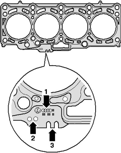
42.6. Cylinder head gasket markings 1. Part number; 2. Marking holes; 3. Production control code
Article reprinted from the website SKODABOOK.RU