



Note: When removing the cylinder head, the engine temperature must not exceed 35°C, otherwise the cylinder head may become deformed after its bolts are loosened.
1. The installation details of the cylinder head, vacuum pump and CMP sensor are shown in the illustration.
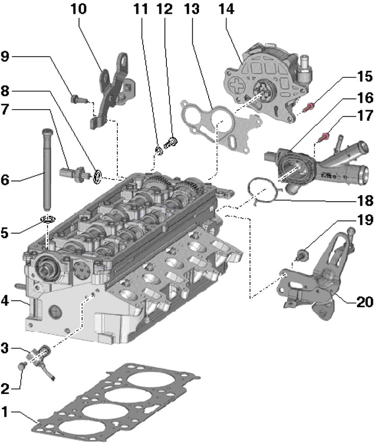
39.1. Installation details of the cylinder head, vacuum pump and CMP sensor 1. Cylinder head gasket, subject to replacement; 2, 15. Bolt, 10 Nm; 3. CMP sensor "G40"; 4. Cylinder head; 5. Bolt washer 6; 6. Cylinder head mounting bolt, subject to replacement, before tightening, insert washers 5 into the cylinder head; 7. D/V "F1" engine oil pressure, with green marking, 0.5 bar, 22 Nm; 8. Sealing ring; 9, 19. Bolt, 20 Nm; 10, 20. Lifting eye; 11. Sealing ring; 12. Threaded plug of oil line, 14 Nm; 13, 18. Gasket, subject to replacement; 14. Vacuum pump; 16. Connection with ECT sensor; 17. Bolt, 9 Nm
2. To replace the CMP sensor, remove the top engine cover and timing belt, then disconnect the sensor connector, unscrew its mounting bolt and release the wiring from the opening by breaking the holders with a screwdriver. When installing, secure the wiring in the opening with a rubber cover from the repair kit.
3. To remove the vacuum pump, remove the air cleaner (see Chapter 4), disconnect the vacuum line from the pump, move the left air pressure tube to the side and unscrew the pump mounting bolts. Use a new vacuum pump seal when installing.
4. Remove the air cleaner together with the MAF sensor "G70" and the intake hose (see Chapter 4).
5. Remove the battery and its holder (see Chapter 5).
6. Remove the casing together with the radiator fans "V7" and "V35" (see Chapter 3).
7. Remove the cylinder head cover (see Section 38).
8. Disconnect the connector (2 in the illustration) throttle module, unscrew the probe mounting bolt (4) and disconnect the vacuum line from the vacuum pump.
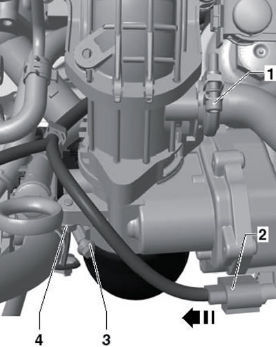
39.8. Throttle valve connector (2) and oil dipstick connection bolt (4)
9. Remove the bolts (2, 5 and arrows in the illustration), release the wiring and hoses on the left air pressure pipe, loosen the clamp (3) and remove the left air pressure pipe.
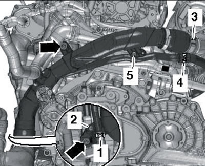
39.9. Removing the left air tube
10. Remove the bolts (arrows in the illustration) and remove the pulsation damper (2). Drain the coolant (see Chapter 3).
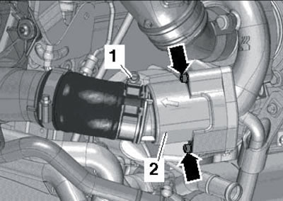
39.10. Damper bolts (arrows) (2)
11. Disconnect the connector (4 in the illustration) eCT sensor "G62", loosen the clamps (1 and 2) and remove the coolant hoses from their fittings.
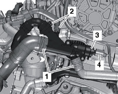
39.11. Connector (4) of the ECT sensor and clamps (1 and 2) of the coolant hoses
12. Disconnect the connector (1 in the illustration) D/V "F1" engine oil pressure, unscrew the bolt (arrow) and remove the vacuum hose (2).
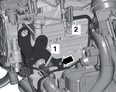
39.12. Removing the vacuum hose (2)
13. Remove the electrical wiring connector (3 in the illustration) from the bracket and disconnect. Release the wiring lines on the turbocharger.
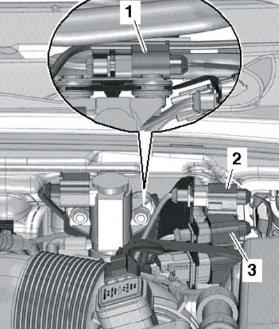
39.13. Electrical wiring connector (3)
14. Remove the bolts (arrows in illustration 35.7) from the boost air tube. Release the coolant hose (3), loosen the clamp (2), disconnect the connector (1) of the boost air pressure sensor "G31"/IAT sensor "G42" and remove the boost air pipe.
15. Remove the EGR connecting pipes (And in the illustration), using the XZN10 bit. The corrugated part of the connecting tube must not be kinked or overtightened.
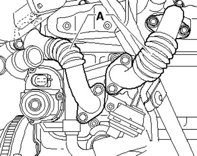
39.15. EGR connecting pipes
16. Give the nuts (arrows in the illustration) particulate filter bracket (A) on the cylinder block.
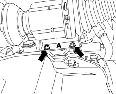
39.16. Particulate filter bracket nuts
17. On CFHC and CLCB engines, remove the bolts (5 and 10 in the illustration), loosen the union nut (2) and set the oil feed line (1) back. Unscrew the bolt (4) and remove the bracket (3).
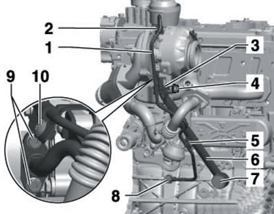
39.17. Removing the bracket
18. On the CFJA engine, remove the bolt (1 in the illustration), loosen the union nut (2) and set the oil feed line back. Loosen the turbocharger support bolt (3).
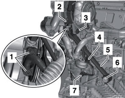
39.18. Parts on the turbocharger
19. Unscrew the bolt (see illustration) rear timing belt cover, loosen the clamp between the turbocharger and the diesel particulate filter.
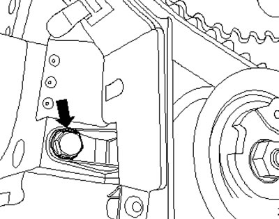
39.19. Timing belt rear cover bolt
20. Remove the bolt from the bracket on the cylinder head (see illustration) and push the particulate filter to the side.
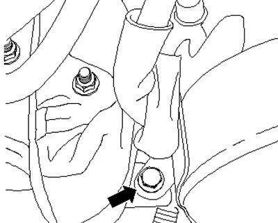
39.20. Cylinder head bracket bolt
21. Disconnect the CMP "G40" sensor connector (see illustration).
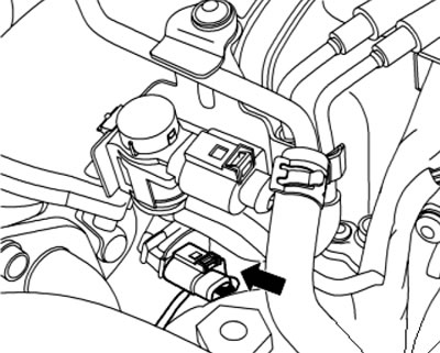
39.21. SMR sensor connector
22. Remove the timing belt from the camshaft (see Section 36).
23. Remove the camshaft gear and its hub using the T10052 puller.
24. Remove the timing belt tension roller nut.
25. Remove the cylinder head mounting bolts in the following sequence: (1-10 in the illustration). Make sure all hoses, pipes and wiring are disconnected from the cylinder head.
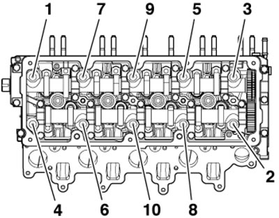
39.25. Sequence of unscrewing the cylinder head mounting bolts
26. To remove the cylinder head you will need an assistant. When the cylinder head is raised, the timing belt tensioner pulley is pulled off the stud and the turbocharger oil return line is pulled out of the support. When removing the cylinder head, first lift it on the transmission side and remove it from the rear timing belt housing, preventing the timing belt tensioner roller from falling. Lay the cylinder head down, preventing the oil return pipe from being deformed. If necessary, place a wooden block under the exhaust manifold. If the cylinder head is removed with the glow plugs, do not lay it on the lower mating surface.
27. Place a clean cloth on the cylinder block to prevent dirt from getting into the oil channels and between the pistons and cylinder walls. Carefully clean the mating surfaces of the cylinder head and block. In doing so, avoid damaging the mating surfaces. It is recommended to use a chemical remover to remove sealant and grease.
28. Determine the deviation of the lower mating surface of the cylinder head from flatness. If this value is more than 0.1 mm, replace the cylinder head. Mechanical treatment of mating surfaces is not permitted. Clean the threaded holes. Make sure there is no oil or coolant in the threaded holes of the cylinder block, otherwise the cylinder block may crack when tightening the bolts.
29. Place the new gasket on the cylinder block so that the part number or "top" mark on the gasket is legible.
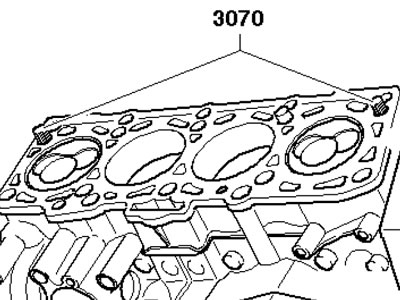
39.29. Guide pins
Note: Do not remove the gasket from its packaging until you are ready to install the gasket; handle the gasket with care. The markings on the new gasket must match the markings on the old gasket (see Section 41). To center the gasket, you can screw guide pins MP1-208 or No. 3070 into the cylinder block (see illustration).
30. Before installing the cylinder head, remove the crankshaft locking device and turn the shaft counterclockwise until the pistons are almost equally positioned below TDC.
Note: Do not remove the open valve guards from the new cylinder head until you are ready to install the cylinder head. If a reversible cylinder head is being installed, lubricate the mating surfaces of the rocker arms and camshaft cams with engine oil.
31. Install the cylinder head. In this case, the tension roller should go onto the studs. Screw in the new cylinder head bolts by hand, then tighten them in sequence (10-1 in Illustration 39.25) in several stages: first with a force of 30 Nm, then tighten to a force of 50 Nm, and finally tighten twice to an angle of 90°.
32. Further installation is carried out in reverse order.