



Removing
Air cleaner assembly components (models 1.6 l)
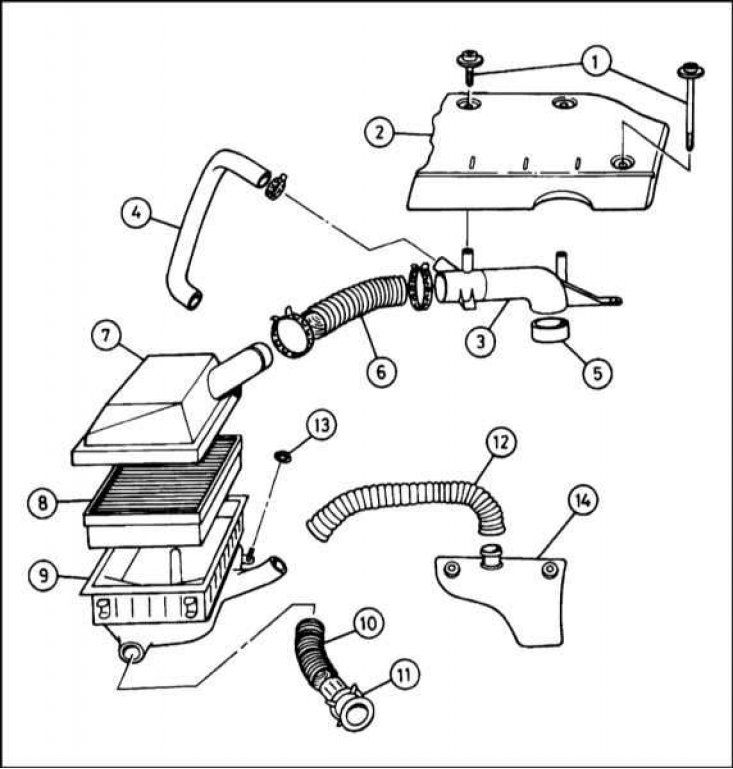
1 - Screws for fastening the cover of the throttle body; 2 - Throttle housing cover; 3 - Receiving knee of the air supply sleeve; 4 - Breather pipe; 5 - Sealing gasket; 6 - Air supply hose; 7 - Top cover of the air cleaner; 8 - Filter element; 9 - Air cleaner casing; 10 - Air intake sleeve; 11 - Nozzle; 12 - Heated air supply hose; 13 - Plastic nut; 14 - Intake air heater cover
Models 1.3 l
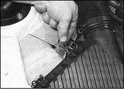
1. Release the wire clamps located around the perimeter of the top cover of the air cleaner.
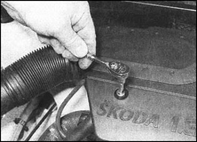
2. Turn out three bolts from a cover of the case of a throttle, then release from clamps on the underside of a cover the hose going to a coal adsorber, and plaits of electroconducting.
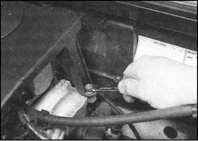
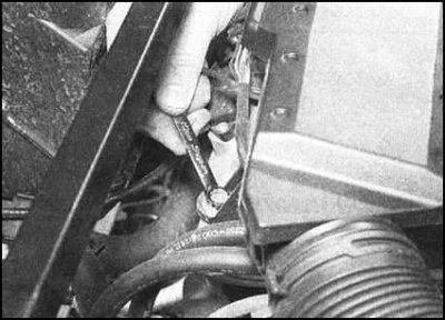
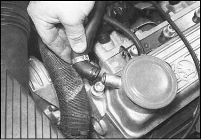
3. Disconnect the ventilation breather pipe from the cylinder head cover...
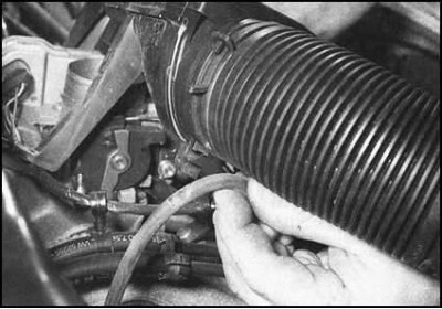
... and release the fuel pressure regulator vacuum hose from the retainer under the intake air duct.
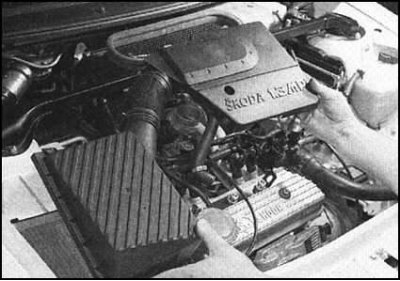
4. Remove the throttle body cover along with the top air cleaner cover and intake duct.
Models 1.6 l
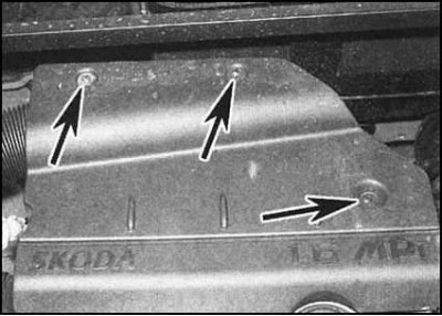
1. Remove the three screws from the cover mounted on the throttle bodies. Note that the front screw is longer than the other two.
2. Release all hoses and wiring harnesses from the retainers on the underside of the throttle body cover. Raise the lid.
3. Loosen the four wire clips around the perimeter of the air cleaner top cover.
4. Disconnect the vent pipe from the top of the intake elbow of the air supply hose. Release from the clamps and move to the side all the wires and hoses that interfere with the removal of the knee.
5. Turn out three fixing screws and remove a knee of a sleeve of air supply together with a sleeve and the top cover of an air cleaner.
All models
1. If equipped, check the condition of the rubber seal installed on top of the throttle bodies. Replace if necessary.
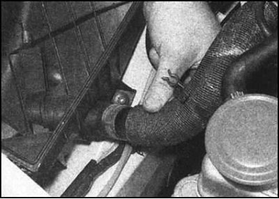
2. If it is necessary to remove the air cleaner casing from the wheel arch mudguard, remove the filter element and disconnect the heated air supply hose from the casing base.
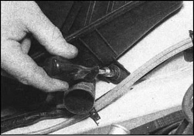
3. The cover is secured with a plastic nut from the front. Two side rubber mounts are inserted into the holes in the wheel arch mudguard.
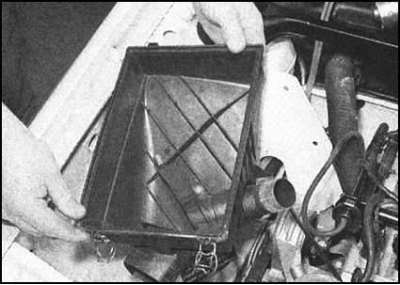
4. Give a nut, release supports from a mudguard and take a casing from an impellent compartment.
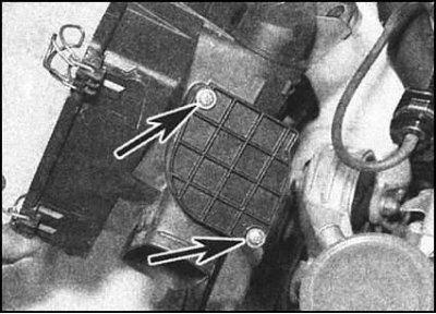
5. The preheated air damper control valve can be removed by loosening the two fixing screws on the front of the casing.
Installation
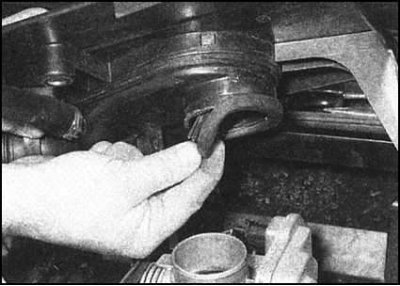
Installation is in the reverse order. The rubber gasket of the throttle body must provide complete air sealing - the slightest leak in the joint can significantly affect the stability of the engine speed.