



Car engine cooling system Skoda Felicia

Cooling and Heating System Specifications
General parameters Maximum pressure in the system, bar 1.2÷1.5 Thermostat Opening temperature (approximately), °C Start of opening 85÷89 Full opening 103 Minimum valve opening, mm 7 Multi-rib drive belt Manufacturers...
General parameters Maximum pressure in the system, bar 1.2÷1.5 Thermostat Opening temperature (approximately), °C Start of opening 85÷89 Full opening 103 Minimum valve opening, mm 7 Multi-rib drive belt Manufacturers...

Cooling system diagram and precautions
Cooling system diagram (1.3L carburetor engine) 1 - Radiator; 2 - Fan; 3 - Temperature sensitive switch; 4 - Outlet pipe; 5 - Water pump; 6 - Cork; 7 - Outlet from the intake manifold to the carburetor; 8 - Outlet from...
Cooling system diagram (1.3L carburetor engine) 1 - Radiator; 2 - Fan; 3 - Temperature sensitive switch; 4 - Outlet pipe; 5 - Water pump; 6 - Cork; 7 - Outlet from the intake manifold to the carburetor; 8 - Outlet from...
Disconnecting and replacing cooling system hoses
Note: Do not disconnect any coolant hoses until the engine has cooled down completely - see the "Precautions" subsection in Section General information and precautions . If, during the performance of the checks listed...
Note: Do not disconnect any coolant hoses until the engine has cooled down completely - see the "Precautions" subsection in Section General information and precautions . If, during the performance of the checks listed...

Removal, condition check and installation of the radiator
Radiator of the cooling system 1 - Coolant supply hose from the engine; 2 - Coolant supply hose from the expansion tank; 3 - Coolant supply pipe from the thermostat housing; 4 - Coolant supply pipe from the expansion...
Radiator of the cooling system 1 - Coolant supply hose from the engine; 2 - Coolant supply hose from the expansion tank; 3 - Coolant supply pipe from the thermostat housing; 4 - Coolant supply pipe from the expansion...

Removal, checking the serviceability and installing the thermostat
Thermostat and related components 1 - From the expansion tank; 2 - Bolt; 3 - Mounting bracket; 4 - To the radiator; 5 - CTS (temperature sensor); 6 - Sealing ring (subject to replacement); 7 - Sealing ring (subject to...
Thermostat and related components 1 - From the expansion tank; 2 - Bolt; 3 - Mounting bracket; 4 - To the radiator; 5 - CTS (temperature sensor); 6 - Sealing ring (subject to replacement); 7 - Sealing ring (subject to...

Checking, removing, installing, disassembling and assembling the cooling system fan
Cooling system fan installation diagram 1 - Radiator; 2 - Upper radiator hose; 3 - Bolt; 4 - Mounting bracket; 5 - Sealing washer; 6 - Temperature sensitive switch; 7 - Lower radiator hose; 8 - Fan casing (diffuser); 9...
Cooling system fan installation diagram 1 - Radiator; 2 - Upper radiator hose; 3 - Bolt; 4 - Mounting bracket; 5 - Sealing washer; 6 - Temperature sensitive switch; 7 - Lower radiator hose; 8 - Fan casing (diffuser); 9...

Checking, removing and installing switches and sensors of the cooling system
Temperature sensitive sensor-switch of the cooling system fan General information The temperature-sensitive switch-sensor switches on the fan when the coolant temperature reaches 95÷99°C. The contacts of the...
Temperature sensitive sensor-switch of the cooling system fan General information The temperature-sensitive switch-sensor switches on the fan when the coolant temperature reaches 95÷99°C. The contacts of the...
Removal, installation, disassembly and assembly of the water pump
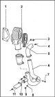
Water pump (design elements) 1 - Gasket; 2 - Water pump; 3 - Nut 20 Nm; 4 - From the radiator; 5 - Drive belt; 6 - Tube; 7 - Screw, 10 Nm; 8 - Sealing ring; 9 - Drain plug; 10 - From automatic start (carburetor); 11 -...
Water pump (design elements) 1 - Gasket; 2 - Water pump; 3 - Nut 20 Nm; 4 - From the radiator; 5 - Drive belt; 6 - Tube; 7 - Screw, 10 Nm; 8 - Sealing ring; 9 - Drain plug; 10 - From automatic start (carburetor); 11 -...

Interior heating/ventilation system — general information
Assembly diagram of the interior heater 1 - Heater fan casing; 2 - Heater casing; 3 - Assembly of control parameters of the heating/ventilation system; 4 - Air duct Schematic diagram of the functioning of the interior...
Assembly diagram of the interior heater 1 - Heater fan casing; 2 - Heater casing; 3 - Assembly of control parameters of the heating/ventilation system; 4 - Air duct Schematic diagram of the functioning of the interior...

Removal and installation of heating and ventilation system components
Models not equipped with air conditioning Assembling the heater casing 1. If necessary, loosen the nuts securing the upper suspension strut supports and remove the strut brace from the vehicle. 2. Acting in accordance...
Models not equipped with air conditioning Assembling the heater casing 1. If necessary, loosen the nuts securing the upper suspension strut supports and remove the strut brace from the vehicle. 2. Acting in accordance...

Air Conditioning System — Information and Precautions
Air conditioning system component connection diagram 1 - Evaporator; 2 - Bottom valve for filling and emptying the system; 3 - Compressor; 4 - Capacitor; 5 - Thermal relay; 6 - Upper valve for filling and emptying the...
Air conditioning system component connection diagram 1 - Evaporator; 2 - Bottom valve for filling and emptying the system; 3 - Compressor; 4 - Capacitor; 5 - Thermal relay; 6 - Upper valve for filling and emptying the...
Removal and installation of air conditioning system components
Attention! Do not attempt to disconnect the refrigeration line under any circumstances! 1. The only procedure that does not require disconnecting the refrigeration lines is replacing the compressor drive belt. A...
Attention! Do not attempt to disconnect the refrigeration line under any circumstances! 1. The only procedure that does not require disconnecting the refrigeration lines is replacing the compressor drive belt. A...
This section is available on russian, bulgarian, belarusian, ukrainian, serbian, croatian, romanian, polish, slovak, hungarian
Read similar sections on other Skoda models
➧ Power unit: Cooling system Skoda Fabia 1 (1999-2007)
➧ Power unit: Cooling system Skoda Rapid 1 (2012-2022)
➧ Diesel engines 1.6/2.0 l: Cooling system Skoda Octavia 3 (2013-2019)
➧ Power unit: Cooling system Skoda Superb 2 (2008-2015)
➧ Power unit: Cooling system (petrol 2.0 l) Skoda Kodiaq 1 (2016-2024)
➧ Power unit: Cooling system Skoda Yeti (2009-2017)
Link to this section in various formats
TEXTHTMLBB Code
- General information
- Maintenance
- Troubleshooting
- Power unit
- Engine in car
- Engine overhaul
- Cooling and heating
- Fuel and exhaust system
- Fuel injection system
- Ignition system
- Transmission
- Clutch
- Manual gearbox
- Drive shafts
- Chassis (running gear)
- Brake system
- Car suspension
- Steering
- Body and interior
- Exterior (external elements)
- Interior (salon)
- Electrical equipment
- Equipment and devices
- Power devices
- Electrical circuits
- General information
- Introduction to guide
- User manual
- Maintenance (petrol)
- Maintenance (diesel)
- Power unit
- Petrol engine 1.3 l
- Petrol engine 1.6 l
- Diesel engine
- Engine overhaul
- Cooling system
- Fuel system (carburetor)
- Central injection (SPFI)
- Multipoint injection (MPFI)
- Diesel power system
- Decreased toxicity
- Engine electrics
- Transmission
- Clutch
- Car gearbox
- Drive shafts
- Chassis (running gear)
- Brake system
- Car suspension
- Steering
- Body and interior
- Exterior (external elements)
- Interior (salon)
- Doors, locks and windows
- Electrical equipment
- Equipment and devices
- Headlights and lighting
- Electrical circuits