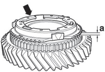
- Check and ensure that there are no scratches or signs of radial wear on the inner friction surface of the synchronizer locking ring (arrow); otherwise, replace.
- The inner ring, outer ring and synchronizer locking ring should be installed in the assembly position on the driven gear and turned.
Note: By "turn" we mean that the synchronizer locking rings should be turned approximately one revolution, applying pressure to them in the longitudinal axis.
- Subsequently, dimension (a) should be measured using feeler gauges in three places, mutually skewed by 120°. Mark the average value.
| Size (a) | Wear limit |
| 1st and 2nd gears | 0.8 mm |
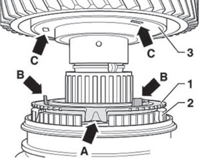
Mount the 1st gear drive pinion onto the driven shaft in the following manner:
- Install the synchronizer locking ring (1) with the three driver protrusions (arrow A) into the recess of the synchronizer carriage (2).
- Then install the outer ring and inner ring into the assembly positions.
- During installation, turn the driven gear of 1st gear (3) so that the protrusions (arrow B) on the outer ring enter the recess (arrow C) of the driven gear.