



Manually controlled gearbox operation diagram
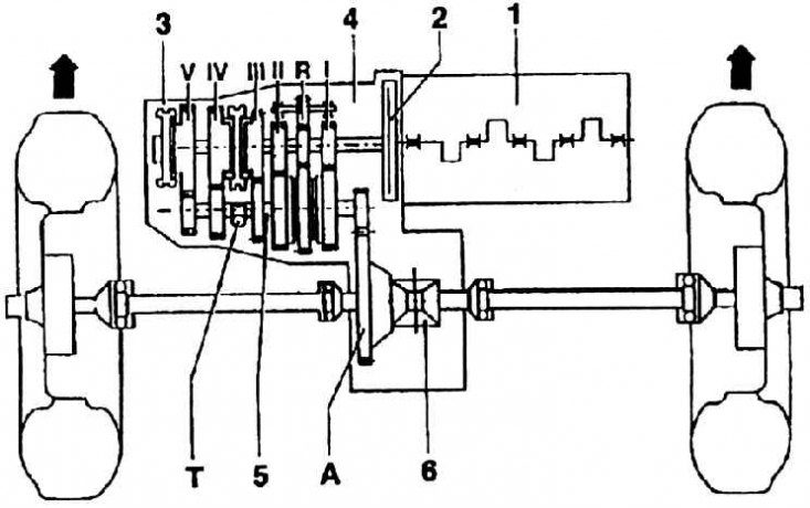
A – cardan shaft drive gear; T – speedometer drive; I – first gear mating pair; II – second gear mating pair; III – third gear mating pair; IV – fourth gear mating pair; V – fifth gear mating pair; R – conjugate pair of reverse stroke; 1 – engine; 2 – clutch; 3 – drive shaft; 4 – manual gearbox; 5 – driven shaft; 6 – differential mating pair
Gearbox disassembly procedure 02K
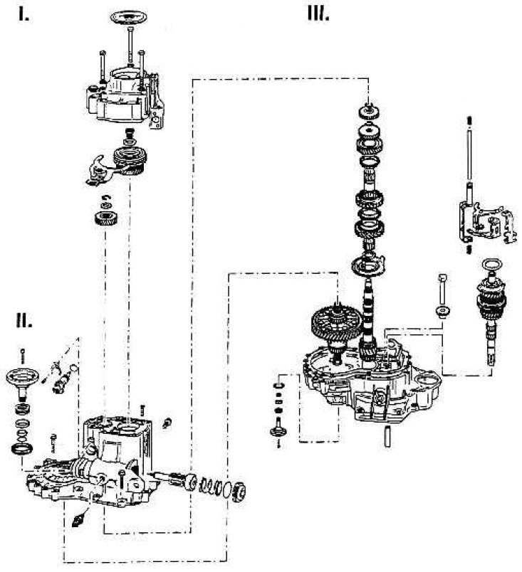
I – disassembling the gearbox housing cover and fifth gear;
II – disassembling the gearbox housing and shift shaft;
III – disassembly of the drive shaft, driven shaft, differential and engagement forks
Gearbox disassembly procedure 02J
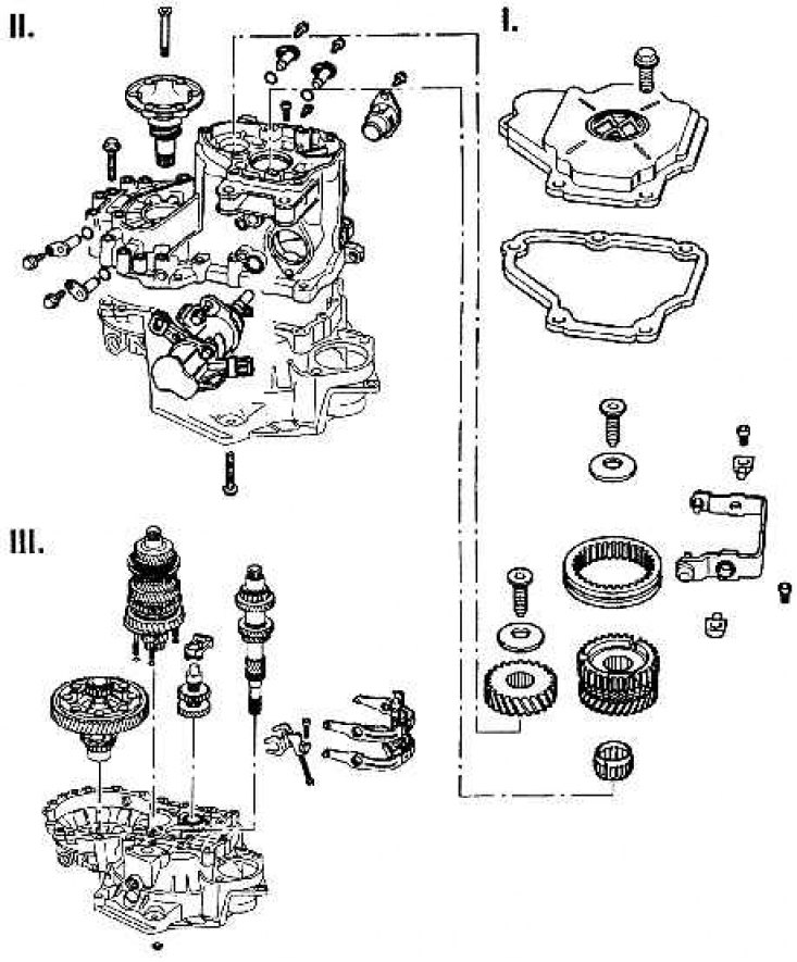
I – disassembling the gearbox housing cover and fifth gear;
II – disassembling the gearbox housing and shift shaft;
III – disassembly of the drive shaft, driven shaft, differential and engagement forks
Gearbox 5-speed
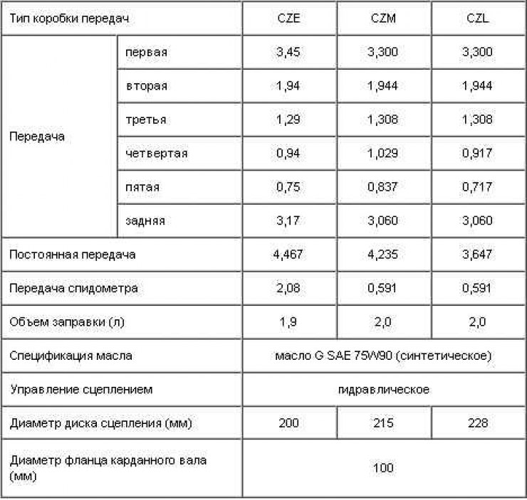
Gearboxes are part of the drive mechanism. The gearbox also includes the transfer case with differential. The gearbox housing is formed from three parts, cast under pressure from aluminum alloy: the gearbox housing, the clutch housing and the gearbox cover.
Mechanically controlled gearboxes have five forward gears and one reverse gear. The gearboxes have two shafts. All forward gears are equipped with locking synchronization; helical gears operate in constant mesh. Forward gear control is provided by a changeover cage of synchronous clutches, controlled by the engagement forks by means of a switching mechanism. The straight-toothed reverse gear is engaged by an intermediate gear, changing the direction of rotation (see Fig. Manually controlled gearbox operation diagram).
The transfer case is located in the remote part of the gearbox housing. Its driven gear, also helical, is located in the cast iron housing of the bevel differential. Cardan drive shafts of unequal length are inserted into the holes of the planetary gears of the differential.
The following figures show the order of disassembling the 02K gearboxes (see fig. Gearbox disassembly procedure 02K) and 02J (see fig. Gearbox disassembly procedure 02J). The gearbox housing part also includes the drive unit mounting element on the left side (in the direction of movement) and, in addition, the switching mechanisms located on the gearbox. In the axis of the drive shaft of the 02K gearbox there is a hole through which the clutch release rod passes.