
Mounting reamer of the shift lever (gear shift 02K)
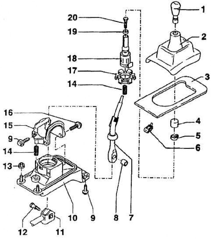
1 - the handle of the shift lever; 2 - tire; 3 - cover; 4 - detail of the handle; 5 - bracket; 6 - holding bracket; 7 - switching lever; 8 - compensation sleeve; 9 - bolt М8х20 (M = 25Nm); 10 – the case of the switching lever; 11 - switching rod; 12 – collar bolt M 8x28 (M = 20 Nm); 13 - self-locking nut M 8; 14 - pressure spring; 15 - bracket; 16 - bolt M 8x20 (M = 25 Nm); 17 - spherical socket; 18 - atteration cartridge; 19 - belt; 20 - bolt
Switching device and the scheme of transmission of movement and power in the gearbox 02K
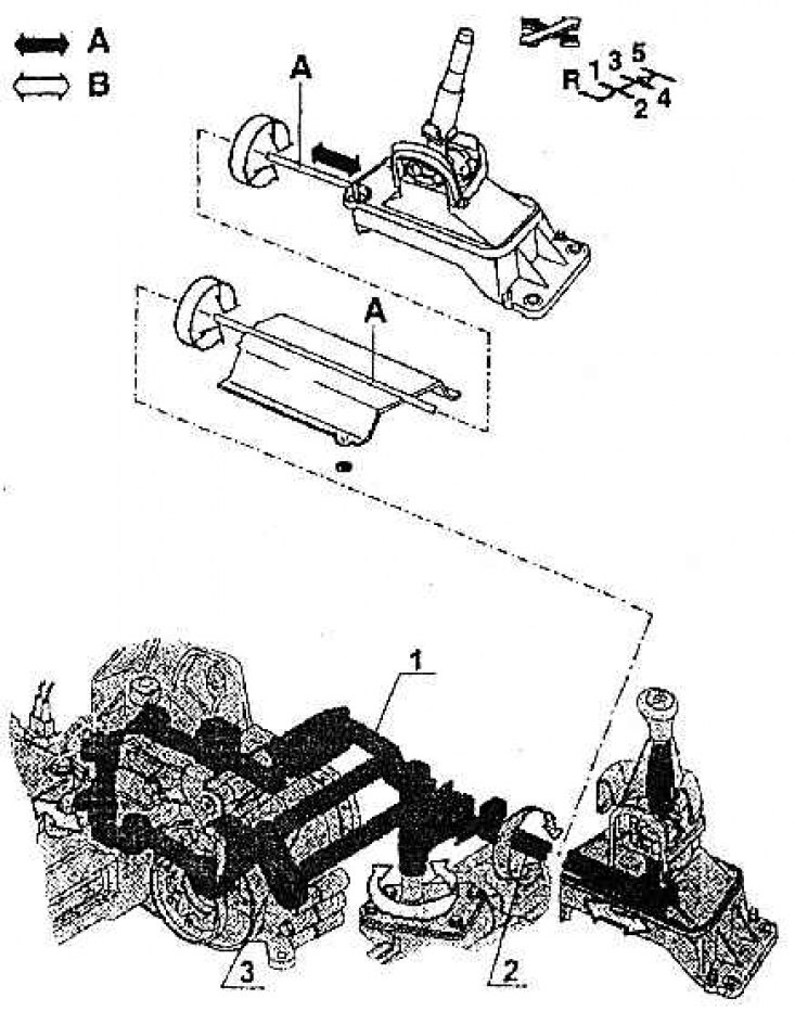
1 - thrust guide; 2 - thrust of inclusion; 3 - connecting rod
On fig. Mounting reamer of the shift lever (gear shift 02K) shows the location of the shift lever and its hinges in the housing. The shift lever housing is bolted to the body center member.
The movement and force is then transmitted by a shift rod attached to the bottom of the shift lever to a shift device mounted on the gearbox. In this device, the movement of the thrust is decomposed into a movement by which a pair of gears is selected, and a movement by which a certain gear is engaged. The switching device is shown in fig. The switching device and the scheme for transmitting movement and power in the gearbox 02K. The choice is made by pulling or pressing the rod, turning it on by turning it. Since the shift pin bracket is bolted to the axle beam, which is firmly connected to the body, the shift lever housing is not connected by another rod. The vibrations of the gearbox are damped by the rods and elbows of the switching device fixed on the gearbox.