
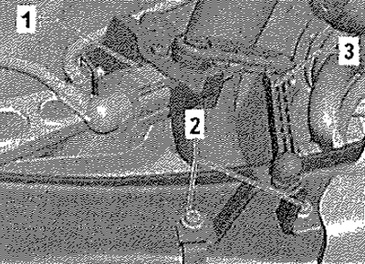
Vehicles with rear left vehicle level sender -G76-
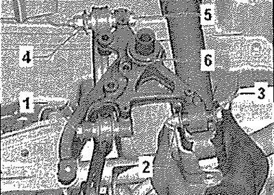
Disconnect connector -1-. Unscrew bolts -2-. Remove rear left vehicle level sender -G76- -3- from control arm.
All
Disconnect connector from speed sensor for ABS. Secure vehicle to hoist with straps -T10038-.
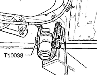
Attention! Otherwise, it may slide off the lift.
Place engine and gearbox jack -VAG 1383 A- -1- under anti-roll bar and raise slightly. Release screws -2- and -3-. Remove engine and gearbox jack -VAG 1383A- -1-.
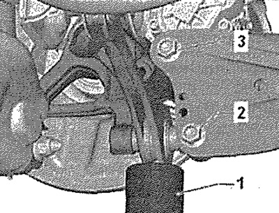
Unscrew lower shock absorber mounting bolt -2-.
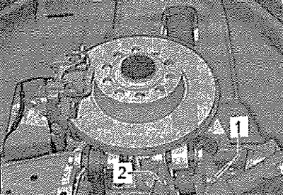
Unscrew lower shock absorber mounting bolt -2-.
Installation
Installation in reverse order.
Note: The stabilizer links, suspension arms and hub may only be screwed on when the dimension "A" between the center of the hub and the lower edge of the wheel arch (curb weight position)! Observe position of trailing arm and wheel bearing housing.
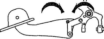
Position of trailing arm and wheel bearing housing
Tightening the bolts of the trailing arm to the wheel bearing housing is possible only after installing all other suspension assemblies (spring and shock absorber must be installed). The wheel bearing housing must be in the curb weight position for tightening. Only then will the trailing arm and wheel bearing housing move into the required position for tightening the bolts -arrows-.
Check wheel alignment.