
Note: If the drive shaft mounting bolt is loosened by more than 90°, the wheel bearing must not be loaded by the weight of the vehicle, i.e. the vehicle must not be on wheels. If the wheel bearing is loaded with the weight of the vehicle when the drive shaft mounting bolt is unscrewed, the inner bearing will be damaged, which will lead to a reduction in its service life. If the vehicle needs to be mounted on wheels or moved, the following must be observed: Install an outer CV joint instead of the drive shaft. Tighten the mounting bolt (use removed) external hinge with a torque of 120 Nm.
Raise a / m. Remove wheel. Remove the brake caliper with the brake hose and handbrake cable connected. Hang the brake caliper on the body so that it does not load the brake hose with its weight. Remove the hub. Remove protective screen. Remove suspension spring.
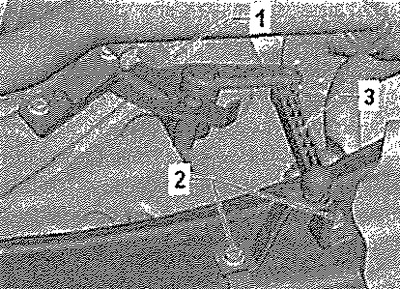
Vehicles with ride height sender -G76-
Disconnect connector -1-. Release screws -2-. Remove vehicle level sender -G76- -3- from transverse link.
All
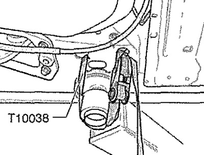
Disconnect connector from speed sensor for ABS. Secure vehicle to hoist with lashing straps -T10038-.
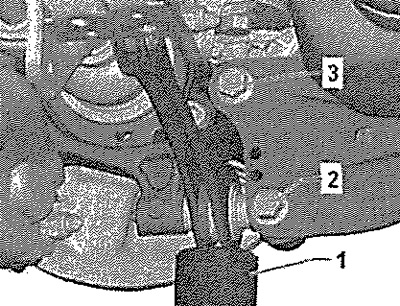
Place engine and transmission jack, eg -VAG 1383A- -1 - under stabilizer bar and support slightly. Remove bolts -2- and -3-. Remove engine and transmission jack, eg -VAG 1383A-.
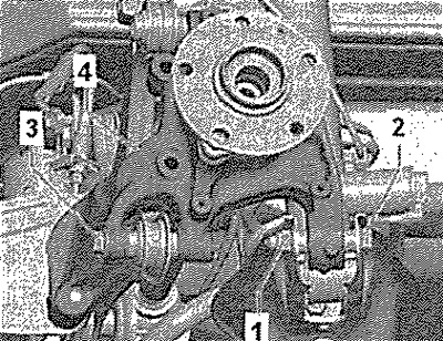
Loosen nut -1-. Unscrew bolt -3- and remove with washers -2- and -4-.
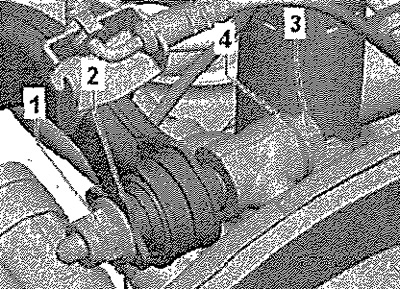
Remove screw -2- and nut -1-. Remove screw -3-. Remove wheel bearing housing -4-.
Installation
Installation in reverse order.
Note: The stabilizer links, suspension arms and hub may only be screwed on when the dimension "A" between the center of the hub and the lower edge of the wheel arch (curb weight position)! Observe position of trailing arm and wheel bearing housing.
Install wheel bearing housing, Install bolt -3- with washers -2- and -3-. Tighten nut -1- by hand. Screw nut -1- onto bolt -2- by hand. Insert bolt -3- and tighten by hand. Place engine and transmission jack, eg -VAG 1383A- -1- under stabilizer bar and support slightly. Tighten bolts -2- and -3- by hand. Install a protective screen. Install hub.
Attention! The wheel bearing housing must be in the curb weight position for tightening.
Tighten nut -1- to specified torque. Tighten nut -1- and bolt -3- to specified torque.
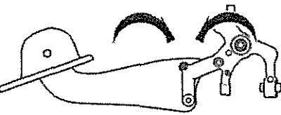
Installation position of trailing arm and wheel bearing housing
Tightening the bolts of the trailing arm to the wheel bearing housing is possible only after installing all other suspension assemblies (spring and shock absorber must be installed). The wheel bearing housing must be in the curb weight position for tightening. Only then will the trailing arm and wheel bearing housing move into the required position for tightening the bolts -arrows-.

Tighten bolts -2- and -3- to specified torque. Check wheel alignment.
Vehicles with ride height sensor
Carry out basic headlight setting.