
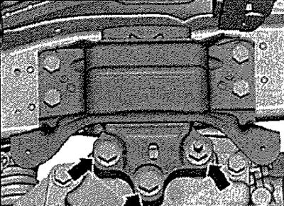
Checking the position of the power unit supports
The following dimensions must be observed, between the engine support -1- and the engine bracket there must be a distance -a- = 10 mm; the cast edge of the engine mount bracket must be parallel to the engine mount console; size -b-= size -b-.
Note: The distance -a- = 10 mm can be turned with a suitable round material, for example.
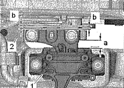
If these distances are greater or less than specified, it is necessary to adjust the supports of the power unit.
Power unit mount adjustment
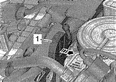
Remove the plenum box cover. Remove engine cover. Unlock catch -arrow- and remove retainer -1- for engine cover. Remove battery with bracket -1-. Remove the caps on the threaded connections of the cups of the front shock absorber struts. Place adapter -MP9-200/18- with hook -MP9-200/10- on cross member -T30099- with support -10-222A/31-.
Position crosshead -T30099- with support -10-222A/31- and support -T30119- on the screw connections of the front suspension strut cups as shown in the illustration. Tighten the power unit evenly with the spindle, but do not lift. Unscrew bolts -arrows- for engine mounting one by one and replace them if this was not done when installing the engine. Bolts first only bait.
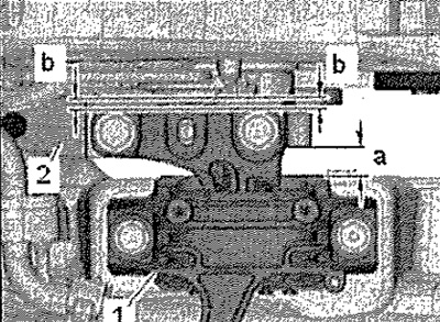
Move the power unit back using a pry bar until the following clearances are reached: there must be a distance between the engine support -1- and the engine bracket -a- = 10 mm; The molded edge of the engine mount bracket must be parallel to the engine mount bracket. Size -b- = size -b-.
Note: The distance -a- =10 mm can be checked, for example, with a suitable round material.
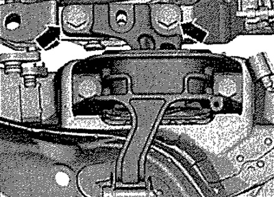
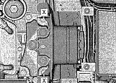
Tighten the engine mount bolts. Unscrew bolts -arrows- for gearbox support -1- one by one and replace them if this was not done when installing the engine. Bolts first only bait.
Check the parallelism of the ribs of the console and the gearbox supports from the gearbox side. Size -x- = size -x-. Tighten gearbox mounting bolts.
Installation in reverse order.