
Note: Depending on the version, the brackets may be different.
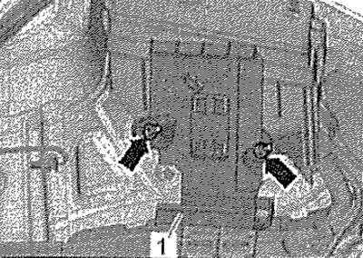
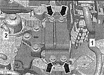
Detach cable guide -1- from mountings and press slightly to one side.
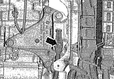
Unscrew nut -arrow- and disconnect earth wire. Remove the plenum box cover. Remove engine cover.
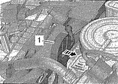
Unlock catch -arrow- and remove retainer -1- for engine cover. Remove the caps on the threaded connections of the cups of the front shock absorber struts. Place adapter -MP9-200/18- with hook -MP9-200/10- on cross member -T30099- with support -10-222A/31-.
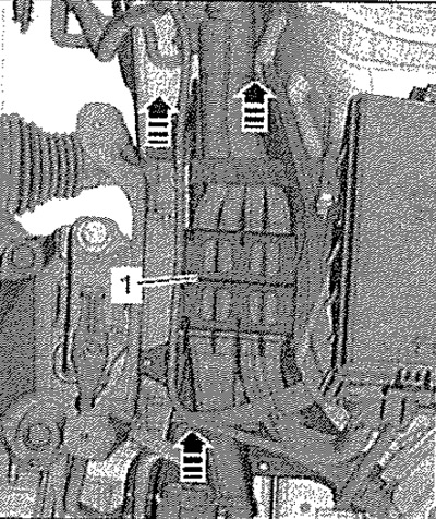
Position crosshead -T30099- with support -10-222A/31- and support -T30119- on the threaded connections of the front suspension strut cups as shown. Tighten the power unit evenly with the spindle, but do not lift. Remove screws -2-, then remove screws -arrows- and remove gearbox support -1-.
Installation
Installation in reverse order.
Note: Replace screws that are tightened to the specified angle.
Screw gearbox support to side member.
Carefully! Risk of damage to the threads in the gearbox console due to uneven installation of the bolts. Before screwing in the bolts, the bracket for the gearbox and console must be absolutely parallel to each other. If necessary, raise the gearbox for this with a jack. Disconnecting the traverse is allowed only after all the threaded fasteners of the power unit support have been tightened to the prescribed torque.
Raise the gearbox evenly using the spindles of the traverse until the bracket for the gearbox comes into contact with the bracket for the gearbox support. Checking the position of the power unit supports. Remove the traverse from the engine.