



Contents: Metal locking lever ⬇ Intermediate lever made of plastic ⬇ Further for all cars ⬇ In the checkpoint of a car with a…⬇ Further for all cars ⬇
Remove the engine cover.
Note: All bandages that are released or cut during removal must be reinstalled in the same places during installation. Additional work must be performed when disconnecting and connecting the battery ground wire.
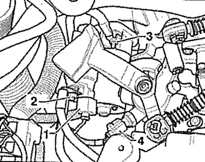
Disconnect the battery ground wire with the ignition off. Remove the battery and battery bracket. Remove the air filter, if installed above the gearbox. Remove the water drain box cover. Disconnect connector "1" on the starter and connector "4" on the reversing light switch. Unscrew the cable fastening "2" on the starter and the ground wire "3". Release the wires. Unscrew the upper starter mounting screws.
Remove the lock washer "see arrow 1" of the gear shift cable from the gear shift lever "A". Remove the gear shift cable from the journal.
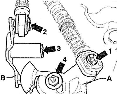
Metal locking lever
Remove the lock washer "see arrow 2" of the gear selection cable from the intermediate lever "B". Remove the gear selection cable from the journal. Remove the lock washer "see arrow 3" from the intermediate lever "B" and remove the intermediate lever.
Note: Lock washers must be replaced.
Intermediate lever made of plastic
To prevent damage to the gear selector cable, separate the drive cable lock from the gear selector cable before removing it. Pull the locking mechanism forward as far as it will go in the "direction of arrow 1" and then lock it by moving it to the left in the "direction of arrow 2". Remove the intermediate lever together with the drive cable lock.
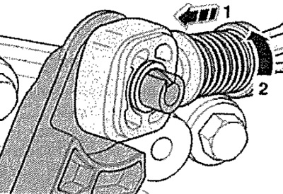
Further for all cars
Remove the gear shift lever "A" by unscrewing the nut "see arrow 4".
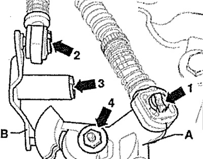
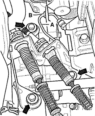
Remove the drive cable counter support from the gearbox "see arrows" and tie it together with the gear selection cable and the gear shift drive cable on the side from above. Remove the holder "B" from the gearbox and disconnect it from the hose line "A".
Remove the support "see arrows A". Remove the actuator cylinder "see arrows B" and move it to the side, secure it with wire, do not open the pipeline system.
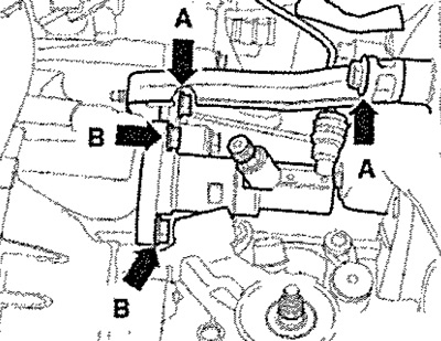
Caution! Do not press the clutch pedal after removing the slave cylinder.
Loosen the left front wheel bolts. Remove the upper engine/gearbox connecting bolts. Install the "T30099" retaining device.
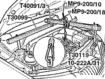
Unscrew the "arrow" nut and remove the ground wire from the gearbox support.
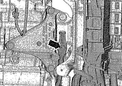
Slightly tighten the engine/gearbox unit by the spindle. Unscrew the mounting screws "see arrows" from the gearbox support.
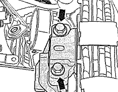
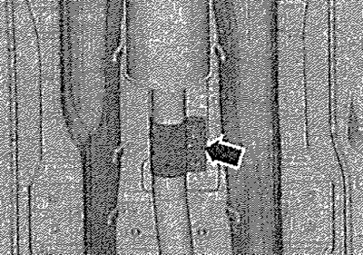
Raise the car. Remove the left front wheel. Raise the car and remove the left front wheel arch cover. Remove the starter. If present, remove the protective cap of the cardan shaft from the engine "see arrows".
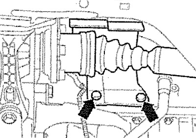
Unscrew the bracket of the muffler inlet pipe "see arrows". Loosen the clamping sleeve "arrow" and disconnect the exhaust system.
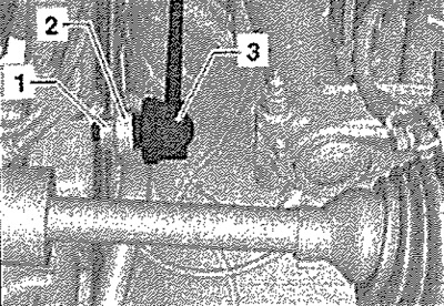
On both sides, unscrew the nut "1" securing the stabilizer rod "3". On both sides, remove the stabilizer rod "3" from the stabilizer "2".
In the checkpoint of a car with a start-stop system
Disconnect the "arrow" connector on the neutral position sensor of the gearbox "G701".
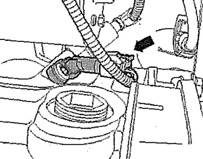
Further for all cars
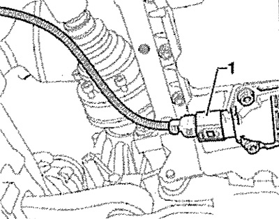
Disconnect the joint shafts from the flange shafts and tie them up as high as possible (without damaging the protective coating). Disconnect connector "1" of the oil level/temperature sensor (if available).
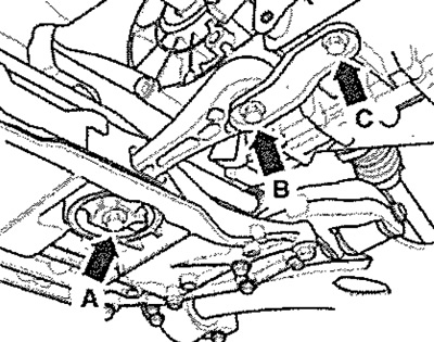
Remove the stabilizer bar post "see arrows A, B and C".
Remove the small flywheel protective shield "A" (if available).
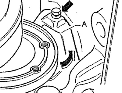
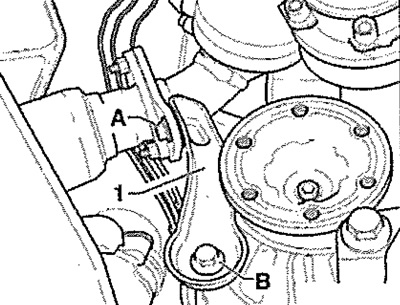
Unscrew screws "A" and "B" and remove support "1" of the exhaust manifold (if available).
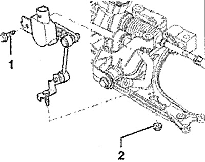
Disconnect the ride height sensor connector (if available). Unscrew nut "2". Unscrew screw "1" and remove the sensor.
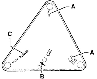
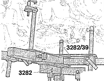
Insert the gearbox mount "3282" into the engine and gearbox lift, for example "VAG 1383A". Install the gearbox mount "3282" and the adjustment plate "3282/39" on the engine/gearbox lift as follows; Place the adjustment plate "3282/39" on the gearbox mount "3282" (the adjustment plate only fits in one position). Align the gearbox mounting brackets with the holes in the adjustment plate. Screw in the fastening elements "A" and "C" as shown on the adjustment plate. Install the engine/gearbox lift under the vehicle, arrow "B" on the adjustment plate points in the direction of travel/vehicle.
Secure the adjustment plate parallel to the gearbox and the gearbox mounting stops. Carefully lower the engine slightly from the gearbox.
Note: When lowering the CP, monitor all pipelines.
Remove the console of KP "A" "see arrows". Remove the lower engine/gearbox connection screws.
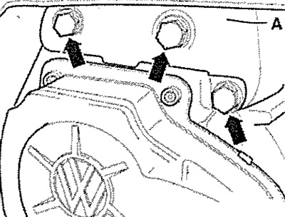
Note: Also unscrew the connecting screw above the flange shaft, if there is one.
Press the gearbox off the relief bushings. Press the engine forward slightly. Turn the gearbox by the gearbox mounting spindles "3282" down and back.
View the original on the website: www.skodabook.ru
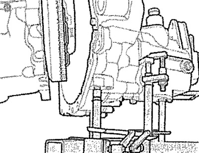
Carefully lower the gearbox, while passing the right flange shaft "A" as shown in the area of the flywheel/intermediate plate. Change the position of the gearbox when lowering by the gearbox mounting spindles "3282".
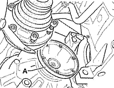
Note: When lowering the CP, monitor all pipelines.