
Attention.
- Make sure that no brake fluid enters the hydraulic control connector.
- If the connector is dirty, clean it thoroughly with a jet of compressed air.
- Do not bend the brake lines near the hydraulic control unit.
Removing
1. Disconnect the negative terminal from the battery.
2. Remove the engine top cover assembly.
For vehicles with common rail diesel engine and particulate filter
3. Remove the decorative engine cover.
4. Remove the cap from the expansion tank of the cooling system.
5. Disconnect wiring harness connectors (1 to 4) particulate filter and lambda probe.
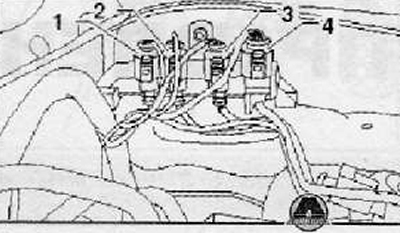
6. Remove the holder together with the wiring harness connector from the cross grille of the air intake and set aside.
7. Disconnect the air inlet and remove the air filter.
8. Remove the ECM from the mounting bracket and set aside.
9. Remove the ECM mounting bracket.
10. Remove the insulating coating from the transverse grille of the air intake.
11. Remove the air intake cross member assembly.
Continuation for all cars
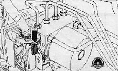
12. Press on the red fuse, shown in the figure below with an arrow.
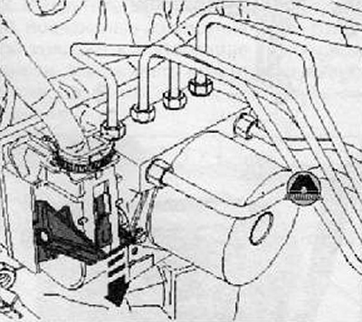
13. Unlock and disconnect by pulling the harness connector from the electro-hydraulic ABS control module as shown in the figure below.
14. Install a special brake pedal lock.
15. Press the brake pedal, move it 60 mm and install a special pedal lock.
16. Connect the hose lowered into the container to the breather on the front left brake mechanism.
17. Open the breather and close only when the brake fluid has completely drained out.
18. Wrap the electro-hydraulic module with a clean cloth. Avoid getting brake fluid on the contacts of the electrical connectors.
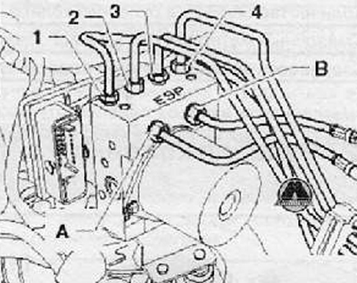
19. Put installation marks on the hydraulic brake pipes (A and B) 20.Unscrew the union nuts and disconnect the brake pipes of the main brake cylinder from the electro-hydraulic module of the anti-lock braking system.
21. Using special plugs from the repair kit (1H0 698 311 A), close the outlets of the brake pipes.
22. Put alignment marks on the brake pipes of the front and rear brake mechanisms (1-4). Then unscrew the union nuts and disconnect the pipes from the anti-lock electro-hydraulic module, as shown in the figure below. Plug the outlets of the brake pipes.
23. Pull the anti-lock electro-hydraulic module with the electronic control unit upwards to remove it from the mounting bracket.
24. Loosen the fastening nuts and remove the mounting bracket for the electro-hydraulic block of the anti-lock braking system (if necessary).
Installation
Note.
- Connect the brake pipes to the electro-hydraulic module of the anti-lock braking system only after removing the special plugs from it.
- Since the electro-hydraulic module is shipped filled with brake fluid, if the plugs are removed before installation, the fluid may leak out, making it impossible to bleed the brake system.
1. Installation is made in reverse order to removal.
Make sure the wiring harness connector is properly connected to the ABS ECU.
Bleed the brake system.
Connect the negative terminal to the battery.