
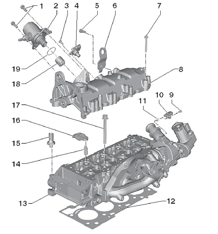
9.1 Installation details and components of the cylinder head and its cover
1 Fuel hose support
2, 11, 12 Bolt, 10 Nm
3 Oil filler cap
4 Cylinder head cover
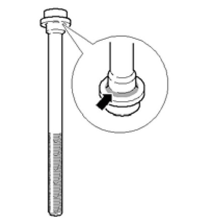
5 Bolt with spacer sleeve and O-ring, 10 Nm
6 Cylinder head cover gasket
7 Lifting eye with knock sensor connector bracket
8, 10.21 Bolt, 23 Nm
9 Front intake manifold support
13 Connection, to heater core
14 Gasket, to be replaced
15 Timing chain tensioner, 50 Nm, do not rotate the crankshaft with the tensioner removed
16 Upper timing chain cover, mounted on sealant D176 501A1
17 Oil seals e / m valves "N205" And "N318" Timing timing adjustment
18, 19 Bolt, 8 Nm
20 Coolant pipe with clamp for vacuum line
22 Timing chain guide
23 Bolt, 23 Nm, installed on fixing sealant D000 600A2
24 Connection, remove before installing the cylinder head
25, 26 O-ring, to be replaced
27 Metal cylinder head gasket, to be replaced
28 Cylinder head
29 Cylinder head bolt, to be replaced, mounted on fixing sealant D197 300A2
2. When installing a remanufactured cylinder head, all mating surfaces between tappets, rocker arms, cams and other friction surfaces must be lubricated before the cylinder head cover is installed. After removing the cylinder head, replace the coolant.
Cylinder head cover
3. Remove the key from the ignition lock.
4. Remove the upper part of the inlet pipeline (see chapter 4).
5. Remove/release all interfering electrical wiring from the cylinder head cover.
6. Loosen the cylinder head cover bolts in sequence (17-1 on resist. illustrations). Finally turn out bolts and remove a cover of a head of cylinders.
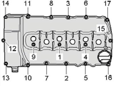
9.6 Tightening sequence of cylinder head cover bolts
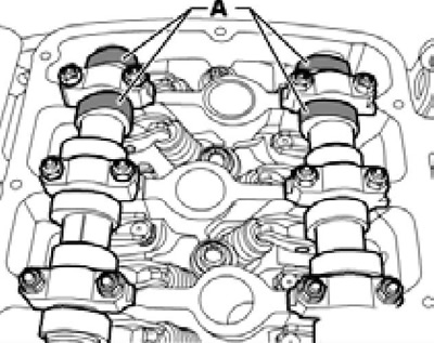
7. Apply to the indicated resist. illustration of the location of the upper cover of the timing chain a little sealant D454 300A2.
9.7 Sealing points
8. Position the cylinder head cover in place and evenly tighten its fastening bolts in the sequence (1-17 in Illustration 9.6) with a force of 10 Nm.
9. Establish the top part of the inlet pipeline.
Vacuum pump
10. Details of the installation of the vacuum pump are indicated on the resp. illustrations.
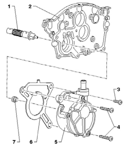
9.10 Vacuum pump installation details
1 drive shaft
2 Upper timing chain cover
3 Short bolt, 8 Nm
4 Long bolts, 8 Nm
5 Vacuum pump
6 Gasket, to be replaced
7 O-ring, not replaceable separately
11. Remove the air duct and air cleaner (see chapter 4).
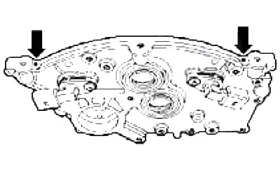
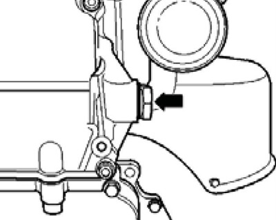
12. Disconnect the vacuum line (And on the opposite illustrations), remove the bolts (arrows) and carefully remove the vacuum pump from the cylinder head.
9.12 Connecting and fixing the vacuum pump
13. Before installation, turn the pump rotor so that the flat sides of the drive shaft enter it, and then evenly slide the pump until it stops.
14. Tighten the bolts and connect the vacuum line.
Cylinder head
15. Wait until the engine temperature drops to at least 35°C, otherwise the cylinder head may be deformed when its bolts are loosened.
16. Disconnect the negative cable from the battery.
17. Remove the right front wheel arch locker (see chapter 11).
18. Cool down (see chapter 3).
19. Remove the air cleaner together with the connecting hose of the throttle module (see chapter 4).
20. Press on the retaining ring and separate the fuel supply line (2 in illustration 5.19).
21. Remove the upper part of the inlet pipeline, then remove its lower part and disconnect the electrical wiring connectors (see chapter 4).
22. Give fixture of the heat-shielding screen and support of the inlet pipeline on a head of cylinders.
23. Disconnect the intake exhaust pipe from the exhaust manifold.
24. Remove the injection pump and pull out its pusher (see chapter 4).
25. Disconnect the connectors of the CMP sensors No. 1 and No. 2 (1 and 3 on resist. illustrations), as well as valves No. 1 for adjusting the phases of the intake and exhaust camshafts (2 and 4). Remove / unhook from the cylinder head all other interfering electrical wiring.
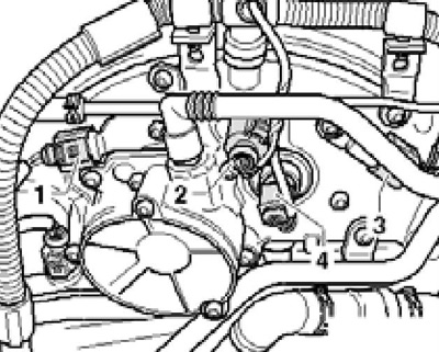
9.25 Wiring connectors on the upper cover of the timing chain
26. Disconnect the coolant hose from the heater core connection. Give fixture of the top and bottom coolant tubes on a cover of a head of cylinders.
27. Remove the vacuum pump (see subsection above).
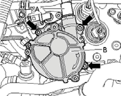
28. Remove three bolts (1-3 per resist. illustrations) at the coolant line connection and remove the cylinder head cover (see subsection above).
9.28 Coolant line connection bolts
29. Turn the crankshaft with support T10172 clockwise until the TDC marks are aligned (see illustration 9.29a). In this case, the camshaft cams for cylinder No. 1 must face each other (see illustration 9.29b).
9.29a Crankshaft in TDC position
9.29b Cam orientation at TDC
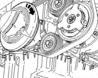
30. Turn out the timing chain tensioner (see resist. illustration).
9.30 Timing chain tensioner
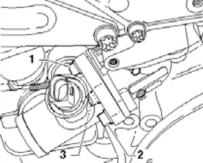
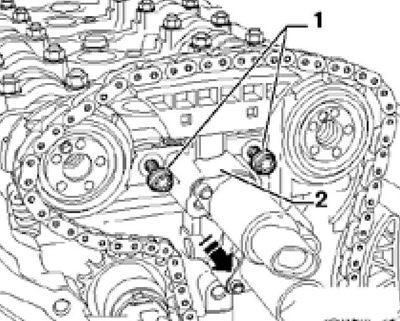
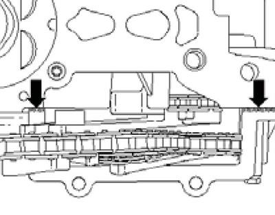
31. Loosen both bolts (1 per resist. illustrations) fastening the lower timing chain cover, and then remove all the bolts (arrows) fixing the upper timing chain cover. Remove the top chain cover.
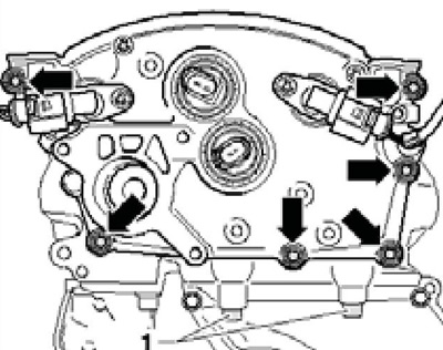
9.31 Bolts for fastening the upper cover of the timing chain
32. When tightening / loosening the timing adjusters, hold the camshafts with an open-end wrench SW27 (see resist. illustration), while template T10068A should not be installed.
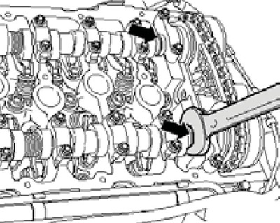
9.32 Holding the camshafts
33. Remove the bolts (1 and 2 on resist. illustrations) fastening the timing adjusters, then loosen the guide (3) and remove the controls. Remove the drive shaft (4) and remove the injection pump drive sprocket (6).
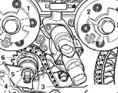
9.33 Fasteners (1 and 2) camshaft adjusters and drive shaft (4)
34. Loosen the cylinder head bolts in the specified resist. sequence illustrations.
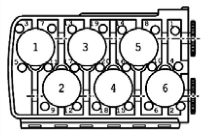
9.34 Cylinder head bolt loosening sequence
35. Remove 4 bolts (1 per resist. illustrations) from the timing case (2) and remove it from the shafts in the direction of the arrow.
9.35 Removing the timing housing
36. Cover the ends of the camshafts (see resist. illustration) pieces of clean paper and wrap them with adhesive tape.
9.36 Protecting the ends of the camshafts
37. Fasten lifting device MP9-201 to the cylinder head as indicated on the resist. illustrations, carefully lift it up and out of the engine compartment.
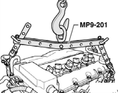
9.37 Removing the cylinder head
38. Check the flatness of the lower mating surface of the cylinder head. The deviation should not exceed 0.05 mm.
39. Make sure piston #1 is at TDC. Otherwise, turn the crankshaft until the marks are aligned (see illustration 9.29a), asking an assistant to guide the timing chain by hand.
40. Lay a clean cloth on the cylinder block so that dirt does not get into the oil channels, as well as between the pistons and cylinder walls. Carefully clean the mating surfaces of the cylinder head and cylinder block. Be careful not to damage mating surfaces. The use of a chemical sealant and grease remover is recommended.
41. Gently remove metal particles and fabric particles. Machining of mating surfaces is not allowed. Clean threaded holes. Make sure that there is no oil or coolant in the threaded holes of the cylinder block, otherwise the cylinder block may crack when the bolts are tightened.
42. Make sure the positions (12 and 20 for resist. illustrations) centering bushings installed.
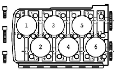
9.42 Tightening sequence of the cylinder head bolts
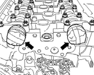
43. Apply 2 mm thick beads of sealant D176 501A1 to the joints of the cylinder head and the lower timing chain cover (see resist. illustration).
9.43 Cylinder head and lower timing chain cover joints
44. Lay a new gasket on the cylinder block so that the part number indicated on the gasket is readable.
Note: Do not remove the gasket from the package until you are ready to install the gasket; handle the gasket carefully.
Fill with a small amount of sealant D176 501A1 both 3 mm holes in the cylinder head gasket located in the area of the previously applied sealant beads.
45. Make sure that the camshafts are in the position shown in illustration 9.29b. Install template T10068A in the slots of both shafts (see resist. illustration).
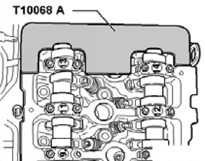
9.45 Locking the camshafts in the TDC position
46. Lay the cylinder head on the centering pins of the cylinder block. Apply to the indicated on the resist. illustration of the surface of the new cylinder head bolts fixing sealant D197 300A2 and insert the bolts. Longer bolts are inserted into the center holes of the cylinder head. Tighten the bolts in sequence (1-20 in Illustration 9.42) in several stages: first with a force of 15 Nm, then with a force of 30 Nm, and then tighten the bolts twice by 90°.
9.46 Place of application of fixing sealant
47. Further installation is carried out in the reverse order to the removal of the remaining components.
48. Finally, fill the engine cooling system (see chapter 3). If necessary, tighten the cylinder head bolts after installation.