



Crankshaft sealing elements, flywheel assembly and oil pump drive with chain tensioner
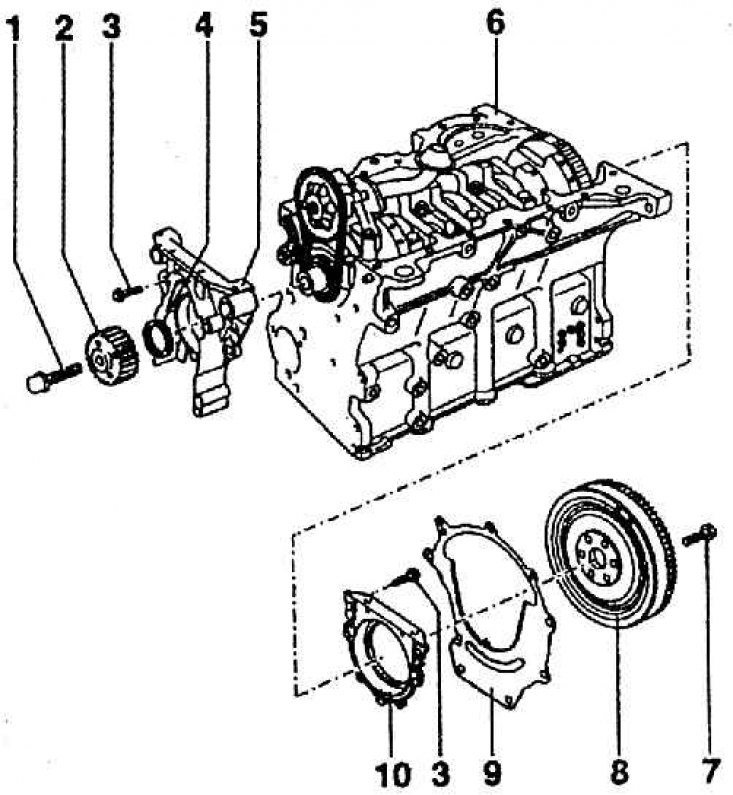
1 – crankshaft timing belt bolt (M = 90 Nm + 90); 2 – toothed pulley of the belt drive for the distribution mechanism drive; 3 – cover bolt (M = 15 Nm); 4 – sealing washer – gufero; 5 – front sealing cover; 6 – engine block; 7 – flywheel bolt (M = 60 Nm + 180); 8 – flywheel; 9 – adapter plate between the engine block and the gearbox; 10 – rear sealing cover with lip washer
The crank mechanism includes: the crankshaft, the flywheel and the connecting rods with assembled pistons.
The crankshaft is made of cast steel. It has eight counterweights. The oil supply channels to the bearings are located transversely (diagonally). At the front of the shaft is a cylindrical end for the toothed pulley of the belt drive, and behind it is the sprocket of the oil pump drive. At the opposite end is a flange with six holes for mounting the flywheel.
The two-piece flywheel absorbs torsional vibrations well, thereby significantly reducing gearbox noise. The flywheel is a unit with a toothed ring for engagement with the starter pinion. It has a working surface for the clutch friction disc, the friction lining of which has an outer/inner diameter of 216/155 mm.
The flywheel is attached to the crankshaft flange with six special bolts with M10x1 threads, fixed with adhesive mastic. The distances between the bolt holes in the flywheel and the shaft flange are uneven in order to ensure the correct position of the flywheel relative to the crankshaft, since they form a dynamically adjusted unit.