Cylinder head assembly (mounting reamer)

1 – a bolt of a cover of the bearing of a cam shaft (M=10Nm); 2 - camshaft drive sprocket; 3 - camshaft drive chain; 4 - regulator of the relative position of the cam shafts; 5 - rubber-metal seal; 6 – a head of the block of cylinders; 7 - exhaust valve; 8 - inlet valve; 9 - sealing washers of cam shafts; 10 – diaphragm of the Hall sensor; 11 - gasket; 12 - bolt; 13 - Hall sensor housing; 14 - bolt; 15 – a bolt of fastening of a gear wheel of the gas-distributing mechanism; 16 - esternya gas distribution mechanism; 17 - sealing washer; 18 - oil scraper cap - gufero; 19 - valve spring; 20 - valve plate; 21 - valve cotters; 22 - hydraulic valve lifter; 23 – a cover of the bearing of a camshaft of inlet valves; 24 - double camshaft bearing cover; 25 – a cover of the bearing of a camshaft of final valves; 26 - camshaft exhaust valves
Installing the cylinder head cover and seal assembly
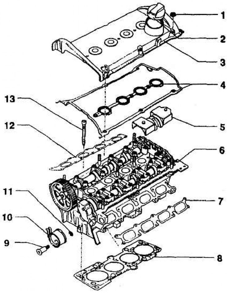
1 – nut of fastening of a cover of a head (M=10 Nm); 2 - plug of the filler neck; 3 – a cover of a head of the block of cylinders; 4 – head cover seal; 5 - oil diaphragm; 6 – a head of the block of cylinders in gathering; 7 - sealing the suction pipeline; 8 – consolidation of a head of the block of cylinders; 9 – a bolt of a tension roller (M = 45 Nm); 10 - tension roller; 11 - gasket; 12 - sealing of the exhaust pipeline; 13 – a bolt of a head of the block of cylinders
The layout of the valves in the combustion chamber of the cylinder head
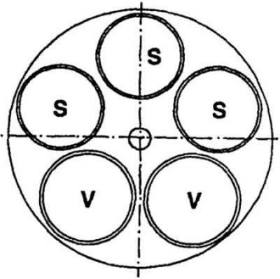
S - inlet;
V - graduation
Location of five valves
1 - inlet valves;
2 - exhaust valves
Section of cylinder head (engine 1.8–92 kW)
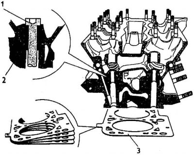
Installing threaded inserts (1) for bolts (2), fastening the cylinder head to the crankcase of the engine.
Detail of a metal seal (3) from several parts under the cylinder head.
The procedure for loosening and tightening the cylinder head bolts
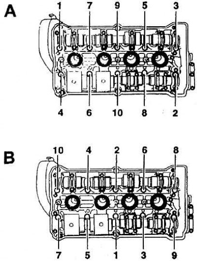
A - the order of unscrewing the bolts of the cylinder head;
B - the order of tightening the cylinder head bolts.
Gear drive of the timing mechanism and coolant pump with a toothed belt
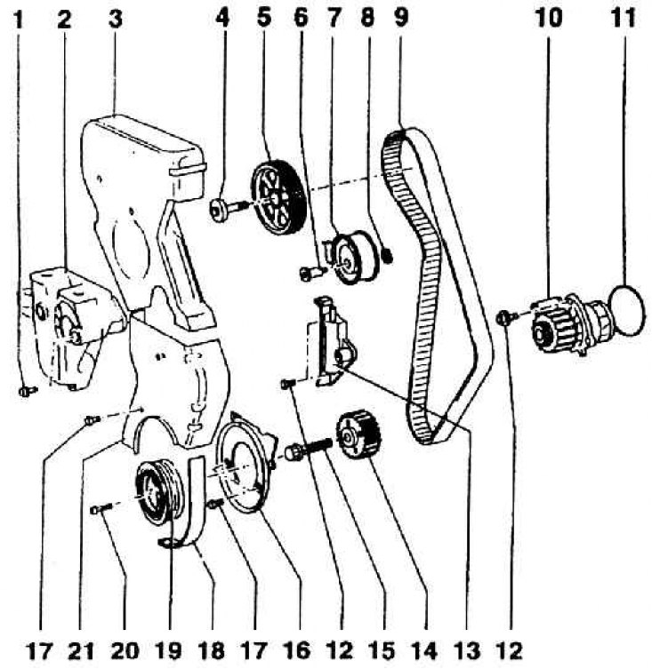
1 – a bolt of fastening of a forward casing of the engine (M = 45m); 2 – a forward casing of the engine; 3 – a casing of a gear belt – an external top part; 4 – a bolt of a pulley of a belt drive of cam shafts (M=100Nm); 5 - a pulley for a belt drive of a camshaft drive; 6 – a bolt of a tension roller (M = 45 Nm); 7 - belt tension roller; 8 - gasket; 9 - toothed belt; 10 - coolant pump; 11 - sealing washer of the pump; 12 - pump fixing bolt (M = 15 Nm); 13 - tension roller housing; 14 - a pulley for a timing belt transmission on the crankshaft; 15 – a bolt of a pulley of a belt drive (M = 90 Nm±90); 16 - the lower inner part of the casing of the belt transmission of the gas distribution mechanism; 17 - casing bolt (M = 10 Nm); 18 - alternator belt; 19 - external multi-ribbed belt pulley; 20 - pulley bolt (M = 20 Nm); 21 – a casing of a gear belt, an external lower part
Alternator belt route
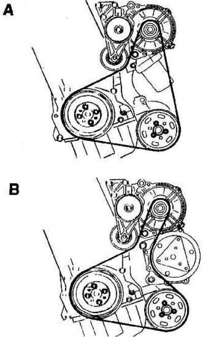
A - in cars without air conditioning;
B - in cars with air conditioning
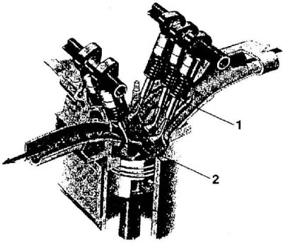
Intake Camshaft Drive Chain Tensioner
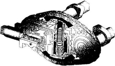
The tensioner allows you to change the rotation of the camshaft and thus the changeability of the intake valves.
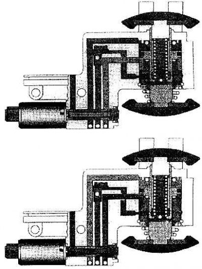
The principle of operation of the hydraulic chain tensioner
The cylinder head itself is made from a heat-treated aluminum alloy casting (Al, Si, Mg) (pic. Cylinder head assembly (mounting reamer), pic. Installing the cylinder head cover and seal assembly). The combustion chambers are not processed. Each combustion chamber has two exhaust and three intake valves (see fig. The layout of the valves in the combustion chamber of the cylinder head, fig. Location of five valves). The exhaust valves have a diameter of 30 mm, the intake valves have a diameter of 27 mm. Intake valve travel 8.4mm, exhaust valve travel 10.3mm. The thread for the M 14 spark plug is located in the center of the combustion chamber at an angle of 3. The design solution of the combustion chamber allows compact combustion of the mixture.
The cylinder head is centered in relation to the engine block with two pins and is attached to it with ten bolts. For bolts, threaded inserts are screwed into the cylinder head. The unevenness of the seating surfaces of the head and block does not exceed 0.1 mm. The head seal consists of four thin profiled sheets (see fig. Section of cylinder head (engine 1.8–92 kW)).
The procedure for loosening and tightening the head bolts is shown in fig. The procedure for loosening and tightening the cylinder head bolts.
Three inlet valve channels are brought together into an oval inlet. The design of the channels allows for the so-called "drum" mixture flow in the cylinder. The channel also allows you to set the coordinates of the twin-beam injectors that direct fuel injection to the three intake valves.
The outlet channels from both valves are reduced to a circular outlet. The flow of coolant in the cylinder head is directed transversely. Approximately - two thirds of the amount of fluid exits the cylinder block on the side of the exhaust ports and near the bosses of the spark plugs. The fluid flow exit from each cylinder is located behind the spark plug well to a longitudinally oriented central cavity. The remaining third of the amount of coolant flows from the side of the intake channels above the combustion chambers to the collection cavity. The arrangement of spaces for the flow of coolant is the same for all cylinders and the same amount of liquid for individual cylinders, which is given by the size of the holes in the cylinder head seal. The coolant leaves the cylinder head on the front side of the head through a plastic neck; with the help of a pipeline located under the suction pipeline, it is fed into the radiator. For completeness, it must be added that from the radiator, the liquid flows through the thermostat housing into the pump and from there into the crankcase of the engine (thermostat sleeve is inserted into the coolant pump housing). The flow through the heating element of the heater or air conditioner is constant.
Both camshafts are placed in the cylinder head in bearings without bushings. The intake camshaft uses a double bearing cap. The camshaft drive is designed in such a way that the timing gear, driven by a toothed belt from the crankshaft gear, is mounted on the camshaft that controls the exhaust valves. To ensure that the belt tension is constant regardless of the thermal expansion of the head and engine block, a pneumatic tension roller is installed (see fig. Drive gears of the gas distribution mechanism and the coolant pump with a toothed belt, fig. Alternator belt route). The intake camshaft is driven by a chain from the exhaust camshaft. The chain is constantly tensioned by a tensioner, which has the function of setting the rotation of the intake valves using the chain of the driven camshaft - we are talking about changing the timing of the intake valves (see fig. The tensioner of a chain of a drive of a camshaft of inlet valves, fig. The principle of operation of the hydraulic chain tensioner). To save weight, the camshafts are hollow and the valve stems are only 6mm in diameter.
Valves have single springs. The transmission of movement and force between the cams of the shafts and the valves is carried out by hydraulic tappets, which automatically set the operating valve clearance (picture of hydraulic pusher see fig. Hydraulic pusher diagram). The landing surfaces of the pushers are subjected to nitrocarburizing.