



Scheme of regulation and control of ignition, fuel, ventilation and gas emission systems of the engine 1.8–92 kW (BOSCH MOTRONIC)
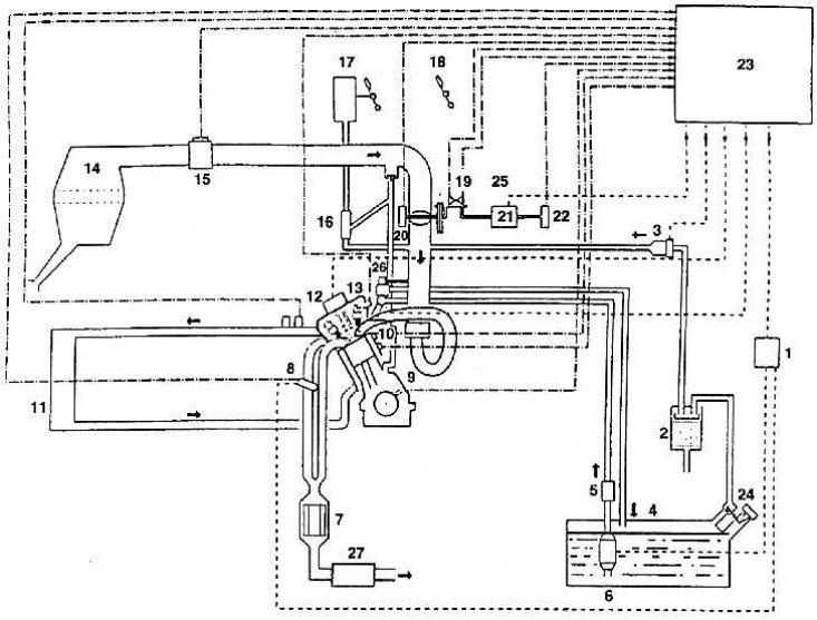
1 – fuel pump relay; 2 – tank with activated carbon; 3 – electromagnetic valve; 4 – fuel tank; 5 – fuel filter; 6 – Electric fuel pump; 7 – adjustable exhaust gas catalyst; 8 – oxygen probe (lambda); 9 – speed sensor; 10 – knock sensor; 11 – radiator; 12 – ignition; 13 – Hall sensor; 14 – supply air filter; 15 – Air mass meter based on the heating wire principle; 16 – Suction jet pump; 17 – brake booster; 18 – gas pedal; 19 – Idle switch; 20 – potentiometer of the actual value of the throttle valve setting; 23 – control unit; 24 – tank deaeration valve; 25 – Throttle control system; 26 – pressure reducing valve; 27 – exhaust muffler
System overview of electronic engine management elements (1.8–92 kW)
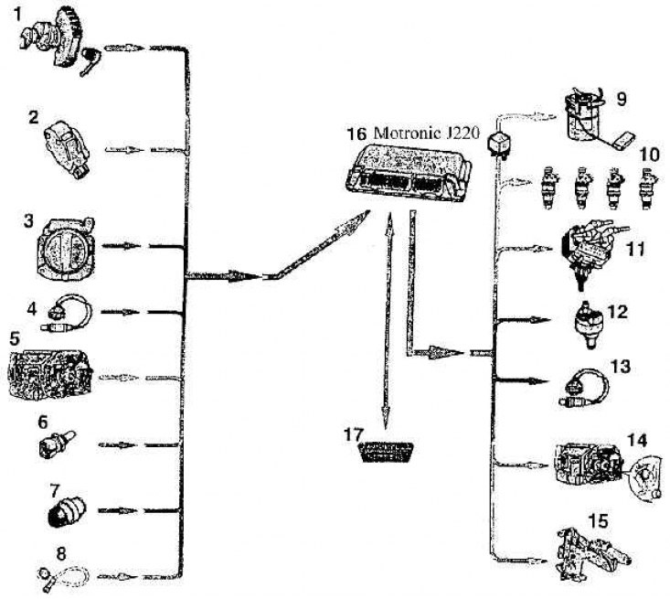
1 – inductive engine speed sensor (G 28); 2 – Hall sensor (G 40); 3 – air quantity sensor (G 70); 4 – lambda sensor (G 39); 5 – Idle speed limit switch (F 60), throttle valve potentiometer for idle speed adjustment (G 88), throttle valve potentiometer (G 69); 6 – heat-sensitive element of incoming air (G 42); 7 – coolant temperature sensor (G 62); 8 – knock sensor (G 66); 9 – fuel pump relay (J 17) and fuel pump (J 6); 10 – injectors (from N 30 to N 33); 11 – ignition coil (N 122) with spark plug 1 (N 128) and spark plug 2 (N 128); 12 – electromagnetic valve of the activated carbon tank (N 80); 13 – lambda probe heating (Z 19); 14 – throttle valve regulator (V 60); 15 – camshaft adjustment valve (N 205); 16 – Motronic control unit (J 220); 17 – diagnostic connector (to connect the tester)