



Valve seat machining
Note: When machining the mating surface of the cylinder head, it is additionally necessary to install deeper (on the size of the cylinder head processing) valves, otherwise they may hit the pistons. At the same time, be careful not to exceed the permissible minimum.
2. Processing of valves and their seats, except for lapping of valves, is not permitted.
3. When repairing an engine with leaky valves, it is not enough to just treat or replace the valve seats and valves. In particular, on engines with high mileage, it is necessary to check the valve play in the guide bushings.
4. If the clearance of the new intake/exhaust valve in the corresponding guide bushing exceeds 0.8 mm, it is necessary to replace the cylinder head, since it is not possible to replace the guide bushings separately.
5. Valve seats should be machined only to the extent necessary to obtain the correct surface. The maximum allowable machining dimensions must be calculated in advance and not exceeded, otherwise hydraulic valve clearance compensation will not be guaranteed and replacement of the cylinder head may be necessary.
6. To calculate the maximum allowable valve seat machining size, insert the valve and press it firmly onto the seat.
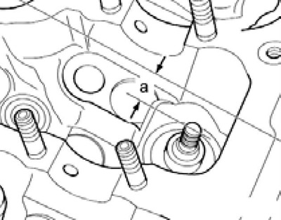
12.6 Determining the distance between the valve and the upper plane of the cylinder head
Note: If valve replacement is required during repair, use a new valve.
Measure the distance between the end of the valve stem and the top surface of the cylinder head (see accompanying illustration) and subtract the minimum size from the result obtained (31.8 mm for short and 10.2 mm for long valves), - will be the maximum machining size for this valve. The dimensions for machining valve seats are specified in the Specifications.
Replacing valve stem seals without removing the cylinder head
7. Remove the camshafts and rocker arms with hydraulic compensators (see Section 11).
8. Remove the spark plugs (see section 14 Chapter 1) and set the piston of the corresponding cylinder to the bottom dead center position.
9. Install tool No.2036 with auxiliary plates No.2036/1 on the cylinder head (see accompanying illustration), screw the T40012/1 adapter with a pressure hose into the spark plug hole and supply air through it under a pressure of at least 6 bar. Using the VW 541/1A lever and the MP1-211/6 pressure plate, remove the valve spring, and then pull out the oil deflector cap using puller No.3364.
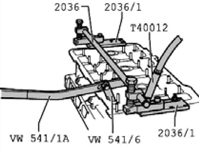
12.9 Removing the oil seal
10. Install the plastic bushing supplied with the oil deflector cap (And on the accompanying illustration) on the valve stem to avoid damaging the cap when installing it. Lubricate the sealing lip of the valve stem seal (B), insert it into the N₂3365 tool and carefully slide it into the guide sleeve through the valve. Remove the sleeve (A), install the valve springs and secure them with the split lock crackers.
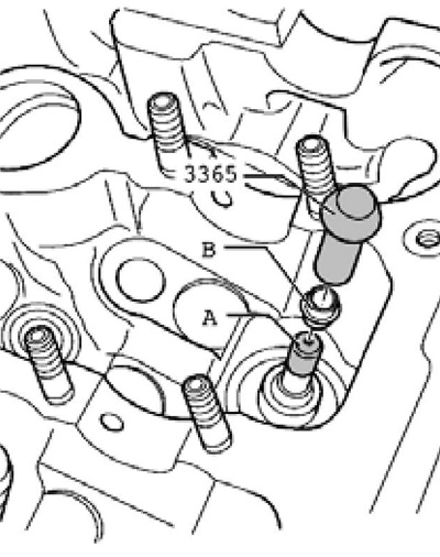
12.10 Installing the oil deflector cap
11. Install the rocker arms with hydraulic compensators and camshafts (see Section 9).