
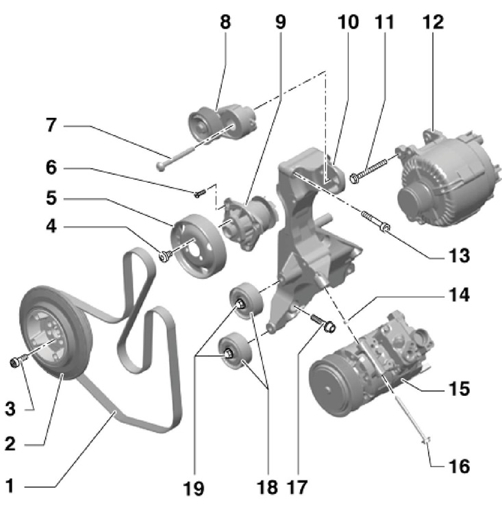
6.1 Mounting and accessory parts
1 Drive belt
2 crankshaft pulley
3 Pulley bolt 2, to be replaced, 60 Nm, then retighten by 180°
4 Bolt, 20 Nm
5 Pump pulley 9
6 Bolt, 8 Nm
7 Tensioner mounting bolt 8, 50 Nm
8 Belt tensioner 1
9 Coolant pump
10 Auxiliary bracket
11 Alternator mounting bolt, 23 Nm
12 Generator
13, 17 Bracket mounting bolt 10, 23 Nm
14 Centering sleeve
15 Climate compressor
16 Bracket mounting bolt 10, 25 Nm
18 Intermediate rollers
19 Bolt, 40 Nm
Drive belt
2. Press the retaining ring and disconnect the vent line (1 in illustration 5.19).
3. Loosen the connection on the back of the EVAP canister. Remove the adsorber from the bracket together with the connected hoses in an upward direction (see resist. illustration) and put it aside.
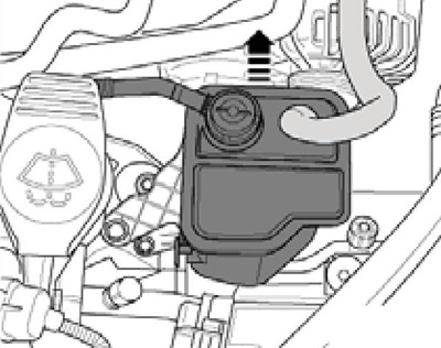
6.3 Removing the EVAP canister
4. Remove the sound insulation under the engine compartment (see chapter 11).
5. If the belt being removed is to be reused, mark the direction of travel on the belt.
6. Pull back the belt tensioner with an open end wrench (1 per resist. illustrations) by the bolt in the direction of the arrow to loosen the belt, and then lock the tensioner by inserting the T10027 bar.
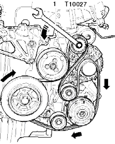
6.6 Locking the drive belt tensioner
7. Remove the drive belt. If necessary, remove the bolt and remove the belt tensioner.
8. Installation is carried out in the reverse order. First, put the belt on the crankshaft pulley, and finish installing the belt on the tension roller. If a used belt is installed, the marks on it must face the direction of travel when the engine is running. Make sure the belt is properly seated on the pulleys.
Auxiliary bracket
9. Remove the right front wheel arch locker (see chapter 11).
10. Remove the accessory drive belt (see subsection above).
11. Remove the generator (see chapter 5).
12. Disconnect the connector (1 in illustration 5.13a) magnetic clutch of the compressor and remove the bolts (arrows). Remove the climate system compressor without disconnecting the refrigerant lines from it, and secure it to the hood lock holder with a wire (And in illustration 5.13b) so that the refrigerant lines are not stretched or kinked.
13. Give the fasteners of the coolant circulation pump bracket "V55".
14. Turn out bolts (1-5 per resist. illustrations) and remove the accessory bracket.
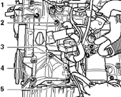
6.14 Fixing the auxiliary bracket
15. Installation is carried out in the reverse order. Tighten bolts by hand first (2 and 4 in illustration 6.14) with centering bushings. Then finger-tighten the bolts (1, 3 and 5) and finally tighten the bolts (1-5) with a force of 23 Nm.