Attention: The presence of metal chips or a large number of small metal particles found during engine repairs may indicate damage to the crankshaft bearings and connecting rods. To prevent further damage from developing, thoroughly clean the oil passages and replace the oil nozzles, oil cooler and oil filter.
Note: If the parts to be removed are to be reused, position them so that they are in the same location and orientation during installation.
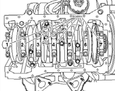
1. Details of installation of a cranked shaft are specified on resist. illustrations. Lay the removed crankshaft so that it does not rest on the rotor of the TFR sensor. Crankshaft machining is not permitted. The selection procedure for main bearing shells is described in paragraph 5.
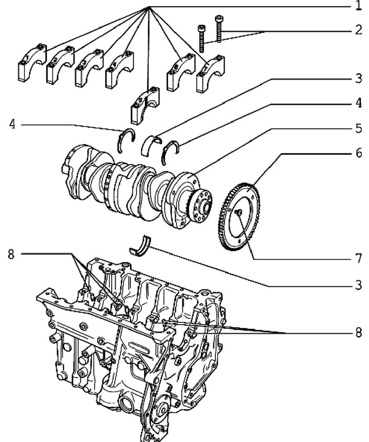
14.1 Installation details of the crankshaft
1 Main bearing caps, #1 - pulley side, #5 - cutouts for washers 4
2 Bolts, to be replaced, 30 Nm, then retighten 180° (no more!)
3 Main bearing shell: with oil groove in the cylinder block, without groove in the cover
4 Support washers for #5 cover
5 Crankshaft with needle bearing
6 The rotor of the SKR sensor, after loosening the bolts, must be replaced
7 Bolt, to be replaced, 10 Nm, then retighten 90°
8 Oil nozzles
2. Details of the installation of the connecting rod and piston group are indicated on the sopr. illustrations.
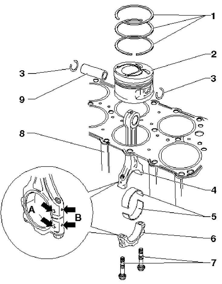
14.2 Installation details of the connecting rod and piston group
1 Piston rings, installed at 120°intervals between locks, mark "TOR" must face the piston crown
2 Piston, 2 deep pockets for valves must face center of cylinder head, arrows must face crankshaft pulley
3 Retaining ring
4 Connecting rod marked A and B (see point 6), can only be replaced when assembled with cover 6
5 Connecting rod bearing shells
6 Connecting rod bearing cap, installed in one position only and only on a paired connecting rod, with a mark "IN " accessories for cylinder and label "A " timing side
7 Cover bolts 6, to be replaced, tighten with lubricated threads and mating surface, 30 Nm, then tighten 90°
8 Cylinder block
9 Piston pin, for easier removal, heat the piston to 60°C
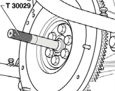
3. To replace the needle bearing in the crankshaft, remove the flywheel and use a suitable puller (see illustration 14.3a) and centering mandrel (see illustration 14.3b). The marking after installation of the bearing must be legible. Press in the bearing to a depth (and in illustration 14.Зb) 2.0 mm.
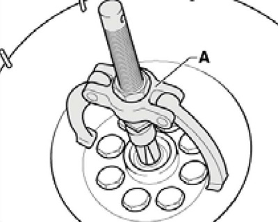
14.3a Removing the crankshaft needle bearing
14.3b Installing the crankshaft needle bearing
14.3c Needle bearing pressing depth
4. On new connecting rods, the connecting rod bearing cap may not be completely broken off from the connecting rod. If it is not possible to break it off by hand, secure the connecting rod in a vice with soft jaws below the fault line (below the center of the hole), unscrew the cover bolts 5 turns and hit the cover with a plastic-faced hammer (see resist. illustration).
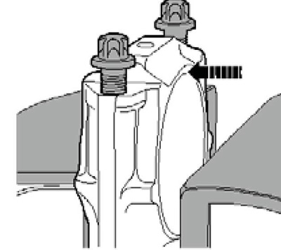
14.4 Separating the connecting rod bearing cap from the new connecting rod
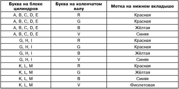
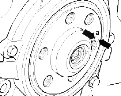
5. After replacing the cylinder block or crankshaft, new main bearing shells should be selected. The thickness of the main bearing shells is marked with colored dots. Liners with yellow marks are always installed in the cylinder block. The marks of the liners installed in the covers are determined by letters on the cylinder block and on the crankshaft (see illustrations 14.5a-b) according to the table below. For example, if the first letters are "H" And "V", then the lower shell of the first bearing should be marked blue.
14.5a Letters on the cylinder block for selecting the lower main bearing shells
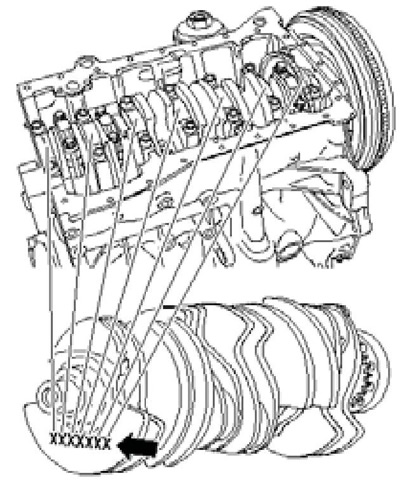
14. 5b Letters on the crankshaft for selecting the lower main bearing shells