
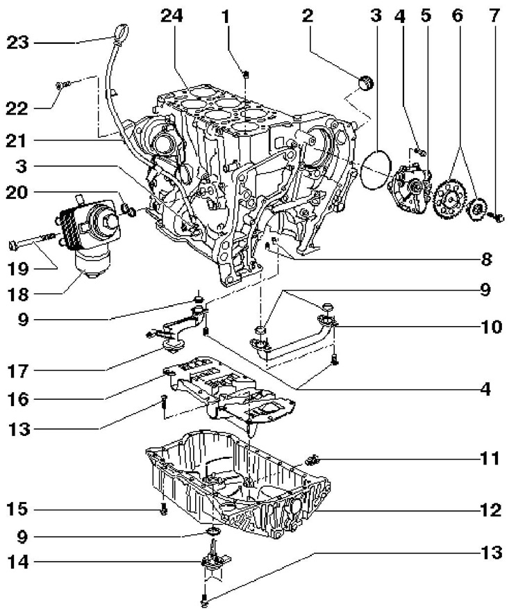
13.1a Parts of the engine lubrication system
1 Return flow control tube, not installed
2 Screw plug, 100 Nm, coat sealing cone with D176 501A1 sealant before screwing in
3, 20 O-ring, to be replaced, lubricate before installation
4 Bolt, 8 Nm, to be replaced
5 Oil pump
6 Oil pump sprockets
7 Bolt class 10.9, to be replaced, 60 Nm, then retighten by 90°
8 Oil jets for main bearings nos. 2-7 and piston cooling, open at 2.0 bar
9 O-ring, lubricate before installing
10 Oil pipe
11 Drain plug, replaceable, 30 Nm
12 Oil pan
13 Bolt, 10 Nm
14 Engine oil level and temperature sensor
15 Bolt, 11 Nm
16 Calming plate
17 Oil pickup
18 Oil filter housing
19 Bolt, 23 Nm
21 Dipstick guide tube 23
22 Bolt, 6 Nm
23 Engine oil dipstick
24 Cylinder block
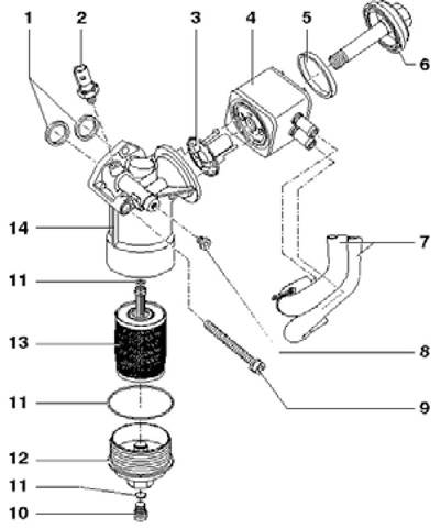
13.1b Oil filter and oil cooler installation details
1,5, 11 O-ring, to be replaced, lubricate before installation
2 Engine oil pressure sensor, 0.9 bar, 20 Nm; cut and replace the seal if it leaks
3 Oil cooler seal with sleeve, to be replaced, lubricate before installation
4 Oil cooler
6 Oil cooler cap, 25 Nm
7 coolant hoses
8 Plug, 15 Nm; cut and replace the seal if it leaks
9 Bolt, 23 Nm
10 Drain plug, 10 Nm
12 Cover, 25 Nm
13 Filter element
14 Filter housings
2. Install the oil cooler seal soaked in engine oil as indicated on resist. illustrations.
Oil pan
2. Remove the sound insulation under the engine compartment (see chapter 11)
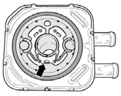
13.2 Installation position of the oil cooler seal
3. Drain the engine oil (see Section 6 of Chapter 1).
4. Disconnect the engine oil level and temperature sensor connector (14 in illustration 13.1a).
5. There is a notch in the flywheel to access the oil pan bolts (And on the opposite illustrations). Turning the flywheel, turn out the head XZN8 three bolts (arrows) in the field of DSG. Then diagonally loosen the remaining bolts and remove them.
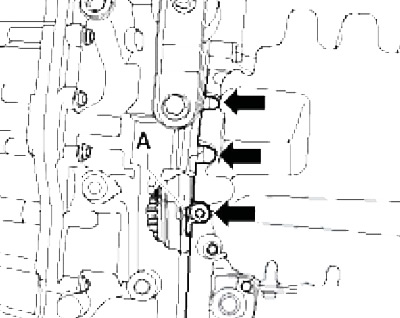
13.5 Unscrewing the extreme bolts of the oil pan
6. Remove the oil pan, tapping lightly with a plastic-faced hammer if necessary.
7. Remove the remnants of sealing materials from the mating surfaces of the cylinder block and oil pan, then clean and degrease them. Be careful not to damage mating surfaces. The use of a chemical sealant and grease remover is recommended.
8. Apply a bead of silicone sealant D176 501A1 with a diameter of 2-3 mm to the mating surface of the oil pan (see resist. illustration) and within 5 minutes after that, install the oil pan by tightening the new oil pan bolts to 11 Nm. Tighten the bolts securing the pan to the DSG with a force of 40 Nm.
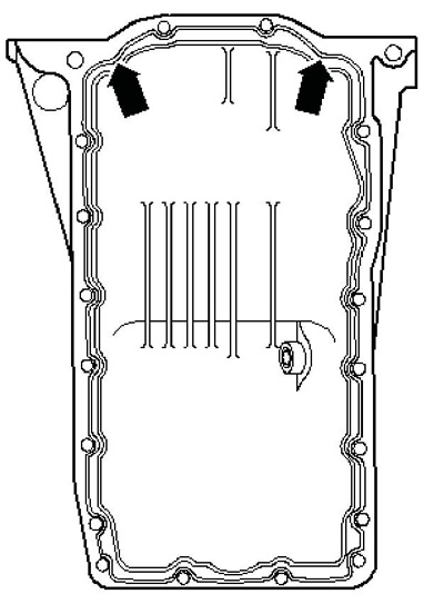
13.8 Sealant application scheme
Note: Do not apply too thick a layer of sealant, otherwise its excess, squeezed inward, may clog the oil pickup.
9. Further installation is carried out in the reverse order. Allow the sealant to dry for at least 30 minutes before adding oil.
Oil pump
Note: When checking the adjusting piston in the oil pump, if the oil pressure is too low, there is no need to remove the pump. adjusting piston plug (tightened with a force of 35 Nm) accessible after removing the plug (2 in illustration 13.1a). To remove the oil pump, the DSG must be removed.
10. Remove the lower timing chain cover (see Section 8).
11. Turn the crankshaft by the pulley until the adjustment marks match: the beveled tooth of the lower sprocket should be on the connection line (And in illustration 11.42), and the protrusion in the hole of the upper sprocket must match the mark (IN) on the cylinder block.
Note: This position is reached every fourth turn.
12. Loosen the bolt (1 per resist. illustrations) stars (2) oil pump, keeping the pulley from turning. Mark the position of the chains in relation to the oil pump sprockets with a carry-on marker.
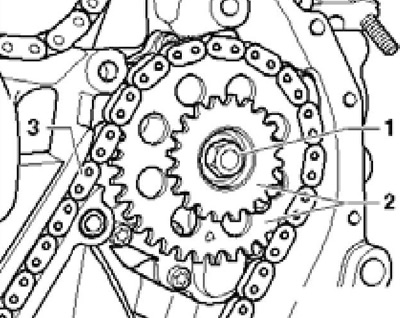
13.12 Oil pump sprocket bolt
13. Turn out the timing chain tensioner (see illustration 9.30), remove the bolts (see resist. illustration) crankshaft chain tensioner and remove it. After that, finally unscrew the bolt securing the sprockets and remove them together with the chains from the oil pump.
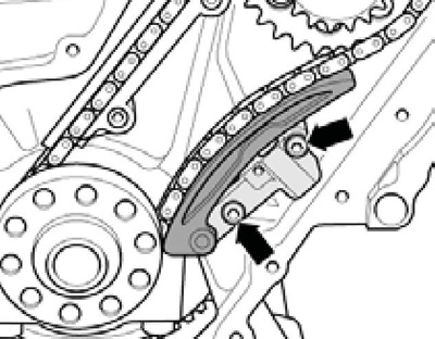
13.13 Crankshaft chain tensioner bolts
14. Turn out bolts of fastening of the oil pump (see resist. illustration).
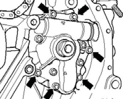
13.14 Oil pump mounting
15. Screw the M10x30 stud into the oil pump shaft, screw the T10055 puller with the T10055 / 3 adapter onto it (see resist. illustration) and remove the oil pump from the cylinder block.
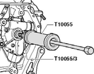
13.15 Removing the oil pump
16. Install the oil pump with new sealing rings and tighten the new bolts of its fastening with a force of 8 Nm.
17. If it is necessary to install a new crankshaft chain, follow the procedure for installing it, as indicated in Section 11.
18. Put the timing chain on the large oil pump sprocket and install it on the oil pump so that the protrusion in its hole matches the mark (B in illustration 11.42) on the cylinder block. In this case, the chamfered tooth of the crankshaft sprocket must remain on the connection line (And in illustration 11.42). In addition, the marks applied when removing the label must match. If you cannot install the large oil pump sprocket, rotate the pump slightly.
19. Put the crankshaft chain on the small sprocket of the oil pump, install it on the oil pump so that the marks made during removal match. Tighten the sprocket bolt by hand.
20. Install the crankshaft chain tensioner. To do this, first loosen the locking tooth in the tensioner with a small screwdriver and press the bar away from the tensioner (see illustration 11.43). Then install the tensioner with the bar pressed out and tighten the bolts (see illustration 13.13) fastening it with a force of 8 Nm.
21. Tighten the timing chain tensioner (see illustration 9.30) with a force of 50 Nm.
22. Holding the crankshaft from turning by the pulley, tighten the new bolt (strength class 10.9) fastening sprockets with a force of 60 Nm, and then tighten it to an angle of 90°.
23. Install the lower timing chain cover (see Section 11).