



Contents: Removal ⬇ Installation ⬇
Note:
Necessary tools, measuring instruments and auxiliary equipment
- Ball joint puller "3287A".
- Torque wrench "VAG 1332".
- Jack for engines and transmission units -VAG 1383 A-.
- Angle tightening key "VAG 1756".
Removal
1. Loosen the hub bolt.
Attention:
- After loosening the hub nut, remove any load from the hub bearings.
- Otherwise, the weight of the vehicle will damage the wheel bearings and reduce their service life.
- While the vehicle is standing on its wheels, the drive shaft bolt can be turned no more than 90°.
- It is prohibited to move vehicles without drive shafts installed, as this will damage the wheel hub bearing. If the vehicle still needs to be moved, the following must be taken into account:
- Install an outer CV joint instead of the drive shaft.
- Tighten the CV joint mounting bolt to a torque of 120 Nm.
2. Unscrew the wheel bolts.
3. Raise the car.
4. Remove the wheel.
Cars with a height sensor
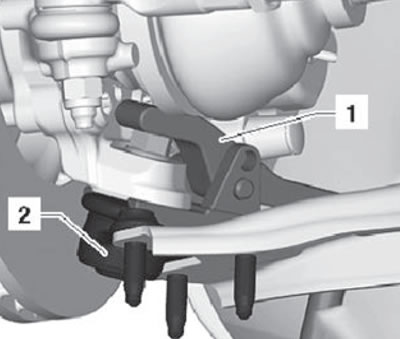
5. Unscrew the fastening nuts (1) shown in the figure below.
6. Pull and disconnect the vehicle height sensor bracket (2) on the left or right side from the front suspension arm (3), as shown in the figure below.
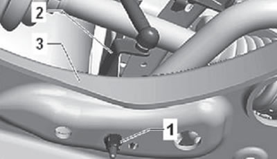
7. Unscrew the arrow nuts as shown in the figure below.
8. Slightly pull the drive shaft out of the wheel hub. Remove the outer joint of the drive shaft from the wheel hub. If the drive shaft cannot be removed from the hub by hand, a special tool must be used to disconnect it.
Note: Before using the special tool, check and make sure that the stop part (1) is installed in the inner part of the device, as shown in the figure below.
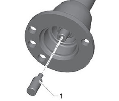
Using a special device:
- Install the special device (1) on the wheel hub, securing it with the mounting bolts (2), as shown in the figure below.
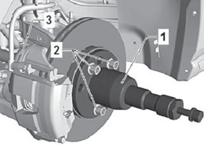
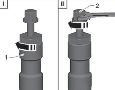
- Pre-tighten the special tool nut (I) by hand. Then, using an open-end wrench, rotate the stop bolt (II) to press the drive shaft out of the front wheel hub, as shown in the figure below.
9. Remove the ball joint from the wishbone.
10. Bend the triangular lever down as far as necessary.
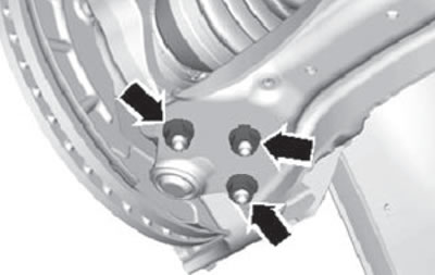
11. Loosen the nut on the conical journal pin a few turns, but do not remove it.
Caution: To protect the threads, leave the nut threaded onto the top few threads of the stud.
12. Install the ball joint puller "3287A" as shown in the figure and press out the ball joint.
Note: Place an engine and transmission jack -VAG 1383 A- or similar device underneath (to prevent accidents caused by the fall of a heavy puller when pressing out a ball joint).
Installation
1. Installation is carried out in reverse order. In this case, take into account the following:
- Insert the ball joint pin into the hole in the steering knuckle.
- Insert the drive shaft into the wheel hub.
- Screw on a new self-locking nut, holding it with a T40 Torx socket wrench.
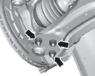
- Tighten the nuts "arrows" shown in the figure below.
Note:
- Check the boot for damage or creases.
- Install the wheel and tighten the wheel bolts to the specified tightening torque.
- Tighten the hub bolt.
Note: The vehicle must not be standing on its wheels during this process, as this will damage the wheel bearings.
[Material is available on the website: skodabook.ru]