



Contents: Removal ⬇ Installation ⬇
Removal
1. Set the steering wheel to the straight-ahead position.
For models with mechanical ignition key
2. Remove the key from the ignition switch to lock the steering column.
For models with electronic ignition key
3. Turn off the ignition and open the front door glass so that the steering column is locked.
4. Disconnect the negative terminal from the battery.
Continued for all car models
5. Remove the instrument panel trim panel from the driver's side (for more details, see the corresponding section in the chapter "Body").
6. Fold the floor covering aside.
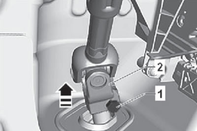
7. Unscrew the connecting bolt (1) from the universal joint (2), then disconnect the joint from the steering rack pinion shaft by pulling it in the direction of the arrow, as shown in the figure below.
Caution: Do not perform the following operations when the steering column shaft is disconnected from the steering gear pinion shaft:
- Connecting the battery.
- Turn on the ignition.
- Turn the steering gear.
- Turn the steering column.
8. Loosen the wheel mounting bolts.
9. Raise the car on a lift. Check and ensure that the vehicle is securely fixed to the lift supports.
10. Remove the front wheels as an assembly.
11. Remove the lower insulation covering of the engine compartment.
12. Remove the insulation covering from the rear of the subframe assembly.
13. If installed, remove the center underbody insulation lining.
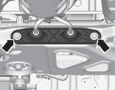
14. Remove the mounting bolts and detach the front section exhaust pipe mounting bracket as shown in the figure below.
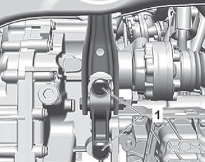
15. Unscrew the mounting bolts (1) of the longitudinal support of the power unit, shown in the figure below.
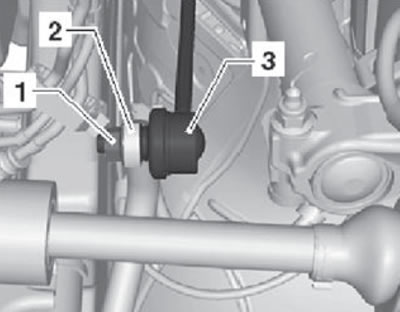
16. Loosen the mounting nut (1) of the anti-roll bar (3), as shown in the figure below.
17. Disconnect the strut (3) from the anti-roll bar (2) on the left and right sides of the vehicle.
Cars with a height sensor
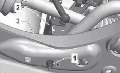
18. Unscrew the fastening nuts (1) shown in the figure below.
19. Pull and disconnect the vehicle height sensor bracket (2) on the left or right side from the front suspension arm (3), as shown in the figure below.
For all cars
20. Loosen the nuts securing the lower arm to the front suspension ball joint, as shown in the figure below.
21. Disconnect the lower arm of the front suspension from the suspension ball joint.
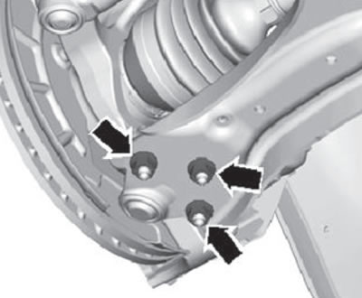
22. Unscrew the bolts that secure the lower arm to the front suspension subframe, as shown in the figure below.
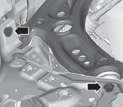
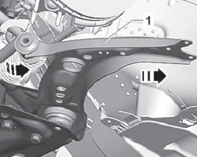
23. Remove the front suspension arm (1) from the subframe and remove the lower arm assembly from the vehicle as shown in the figure below.
Installation
1. Installation is carried out in the reverse order of removal.
Technical condition check
1. Check the lever silent blocks for increased wear and corrosion. If any violations are detected, replace the silent blocks or the lever assembly.
2. Check the lower arm for violation of its geometric parameters. If a defect is detected, replace the lever with a new one.
3. Check all mounting bolts and nuts for defects. If necessary, replace with new ones.
Checking the technical condition of ball joints
1. Before checking the technical condition of the ball joints, it is necessary to check the technical condition of the wheel bearings.
2. Raise the car on a lift and support it under the subframe so that the wheels are suspended.
Note: For accurate measurements, the wheels must be fully suspended.
3. Check the ball joint and its boot for damage. If the boot is damaged, the ball joint must be replaced with a new one.
4. Check the ball joint of the lower suspension arm for runout. To do this, you need to move the wheel up and down with your hands. With this movement, there should be no play between the steering knuckle and the lower suspension arm.
If there is no runout, then the ball joint is in order.
If you feel any vibration when moving the wheel, you need to proceed to the next step.
Caution: Do not use any special equipment to move the wheel or suspension components when performing this operation. Otherwise, the suspension may be damaged.
5. To obtain more accurate data on ball joint wear, it is necessary to use a dial indicator. To do this, the indicator needle must be installed on the ball joint pin.
Note: To improve the quality of measurements, the indicator needle should be installed as close as possible to the vertical axis of the ball joint.
6. When measuring the degree of wear of the ball joint, it is necessary to have an assistant manually move the wheel up and down.
- If the wear value exceeds the maximum permissible value, the ball joint must be replaced.
- If the amount of wear is within the permissible limits, continue checking the technical condition further.