



Contents: Removal ⬇ Installation ⬇
Removal
1. Loosen the nut securing the drive shaft to the front wheel hub.
Attention:
- After loosening the hub nut, remove any load from the hub bearings.
- Otherwise, the weight of the vehicle will damage the wheel bearings and reduce their service life.
- While the vehicle is standing on its wheels, the drive shaft bolt can be turned no more than 90°.
- It is prohibited to move vehicles without drive shafts installed, as this will damage the wheel hub bearing. If the vehicle still needs to be moved, the following must be taken into account:
- Install an outer CV joint instead of the drive shaft.
- Tighten the CV joint mounting bolt to a torque of 120 Nm.
2. Loosen the mounting bolts.
3. Remove the front wheel assembly.
4. Disconnect and remove the brake caliper assembly (for more details, see the relevant section in the chapter "Brake system").
5. Remove the front wheel speed sensor (for more details, see the corresponding section in the chapter "Brake system").
6. Remove the brake disc assembly (for more details, see the relevant section in the chapter "Brake system").
7. Remove the brake hose and sensor wiring harness mounting bracket from the steering knuckle.
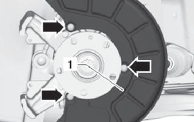
8. Unscrew the mounting bolts and remove the mudguard (1), shown in the figure below.
9. Loosen the nut securing the tie rod end to the steering knuckle. Do not completely remove the nut from the hinge pin.
Caution: To prevent damage to the threaded portion of the tie rod end pivot pin, leave the mounting nut tightened two to three turns.
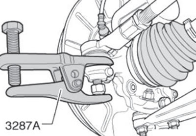
10. Using a suitable puller, disconnect the tie rod end joint from the steering knuckle as shown in the figure below (1). Perform this operation on both sides of the vehicle.
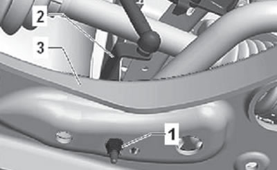
11. Unscrew the fastening nuts (1) shown in the figure below.
12. Pull and disconnect the vehicle height sensor bracket (2) on the left or right side from the front suspension arm (3), as shown in the figure below.
[Text copied from this resource Skodabook.ru]
13. Unscrew the "arrow" nuts shown in the figure below.
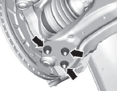
14. Disconnect the triangular lever from the ball joint.
15. Remove the outer joint of the drive shaft from the wheel hub. If the drive shaft cannot be removed from the hub by hand, a special tool must be used to disconnect it.
Note: Before using the special tool, check and make sure that the stop part (1) is installed in the inner part of the device, as shown in the figure below.
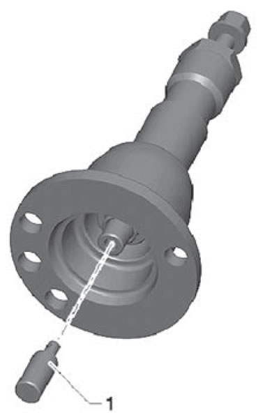
Using a special device:
- Install the special device (1) on the wheel hub, securing it with the mounting bolts (2), as shown in the figure below.
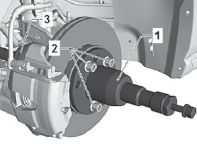
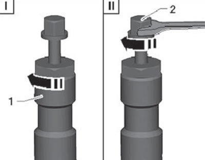
- Pre-tighten the special tool nut (I) by hand. Then, using an open-end wrench, rotate the stop bolt (II) to press the drive shaft out of the front wheel hub, as shown in the figure below.
16. Remove the knuckle from the shock absorber strut with a downward movement and lower it using the engine and transmission jack -VAG 1383 A- until the shock absorber strut is released.
Installation
1. Installation is carried out in the reverse order of removal.