
Crankshaft, its location and seal in the crankcase of the engine
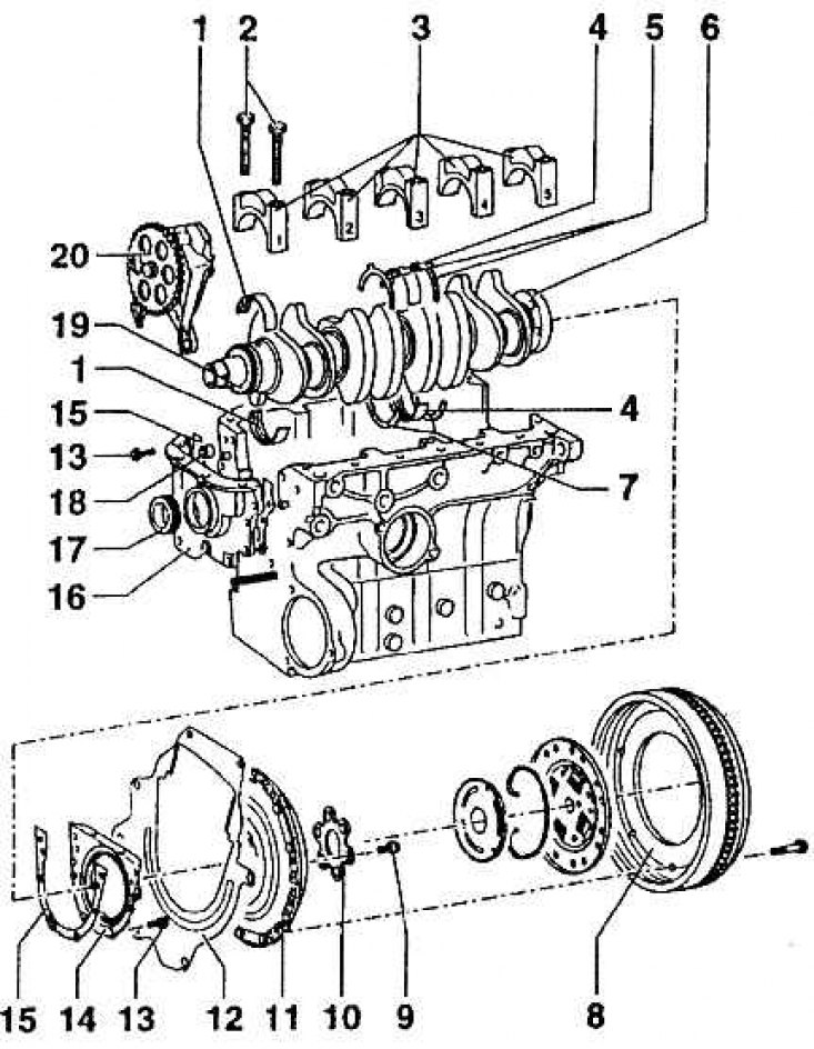
1 - bearing shells I, 2, 4, 5; 2 – screws of covers of bearings of the crankshaft; 3 - bearing caps; 4 - insert of the third bearing; 5 - guide rings for the cover of the third bearing: 6 - crankshaft; 7 - guide ring (Bottom part); 8 - flywheel; 9 - screw; 10 - gasket; 11 - clutch pressure plate; 12 - intermediate plate; 13 – sealing washer screw; 14 - rear sealing flange with sealing gufer-ring; 15 - flange seal; 16 - front sealing flange; 17 - sealing gufer-ring; 18 - sealing gasket; 19 – an asterisk of a chain drive of the oil pump; 20 - oil pump
Mounting reamer of connecting rod and piston
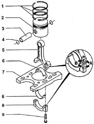
1 - piston rings; 2 - piston; 3 - piston pin; 4 - safety ring; 5 - connecting rod; 6 - insert of the connecting rod bearing; 7 – block of cylinders; 8 – a cover of a head of a rod; 9 - connecting rod screw; A - designation of the sequence of connecting rods; B - designation of the relative position of the connecting rod and the cover
The crank mechanism includes: crankshaft, flywheel and connecting rods with pistons assemblies (see fig. Crankshaft, its location and seal in the crankcase of the engine).
The crankshaft is made of forged steel with machined main and connecting rod journals. At the front of the shaft is a cylindrical surface for the belt pulley, and behind it is the oil pump chain sprocket. At the opposite end is a flange with six holes for mounting the flywheel.
The flywheel forms a single unit with a ring gear designed to engage the engine starter gear. The flywheel has a working surface for a friction clutch disc with a diameter of 200 mm.
The flywheel is attached to the crankshaft flange with six special screws with M10 x 1 thread, fixed with adhesive mastic. The distances of the screw holes in the flywheel and the flange are not uniform in order to guarantee the correct position in relation to the crankshaft, since the assembly must be dynamically balanced. The connecting rods are made from steel forgings. The top lug is equipped with a bronze bushing. The lower lug is detachable and contains a steel sheet insert with a special alloy friction surface. The correct relative position of the connecting rod and the lower part of the eyelet is marked with a core on the sides (see fig. Mounting reamer of connecting rod and piston, designation B), the coordination of the connecting rod to the piston assembly is marked by punching on the surface of the connecting rod and the lower lug (A). The connecting rods are divided into groups by weight and checked for parallelism of both lugs. Pistons are cast from light alloy (Al, Si, Si, Ni, Mg). The working surface of the piston bottom has a profile recess (7.8±0.1mm). Due to this recess, a so-called combustion volume is formed. The arrow on the bottom of the piston must always point towards the belt pulley when assembling.
The top of the piston has three grooves for the piston rings. The top two are sealing, the first with a rectangular section, the second with a blade. The bottom ring is oil scraper. All rings are assembled by the designation "TOR" up.
Pistons are divided into groups according to weight and allowable diameter.
Piston pins steel, hollow with an outer diameter of 17 mm, a relief hole of 10 mm. The pins move freely in the connecting rod and piston eyes. Elastic rings fixed in the piston grooves prevent falling out.