
Engine accessories
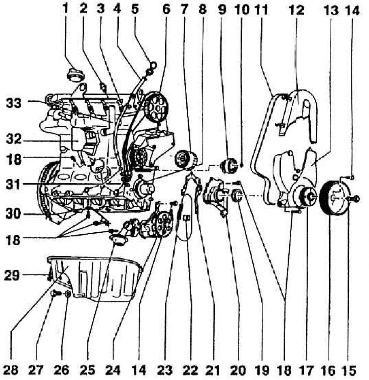
1 - plug of the filler neck; 2 - oil pressure sensor (baroscope); 3 - guide tube of the oil dipstick; 4 - leading part of the oil dipstick tube; 5 - oil dipstick; 6 – a pulley of a belt drive of a cam shaft; 7 - oil filter; 8 – an asterisk of a drive of the oil pump; 9 - tension roller of the timing belt; 10 – a nut of fastening of a tension roller; 11 - toothed belt timing mechanism; 12 – a protective casing of a gear belt (top part); 13 – a protective casing of a gear belt (Bottom part); 14 – a bolt of fastening of a multi-ribbed belt pulley; 15 – a bolt of fastening of a gear belt pulley; 16 - multi-ribbed belt pulley; 17 - belt pulley of a toothed belt drive on the crankshaft; 18 – a bolt of fastening of a casing; 19 - sealing washer; 20 - flange; 21 - flange seal; 22 - sealing tab; 23 - oil pump drive chain; 24 - oil pump; 25 - oil suction screen with overpressure relief valve; 26 - sealing washer; 27 - oil drain bolt from the crankcase (20 Nm); 28 - crankcase; 29 - crankcase mounting bolt (15 Nm); 30 - bracket; 31 - washer; 32 - oil separator; 33 - crankcase breather hose
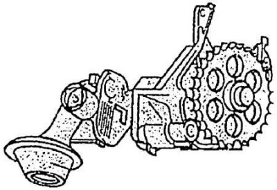
Oil pump
The plastic inlet pipe is assembled on the back of the head. He has four branches with independent conclusions corresponding to the intake holes in the cylinder head. Each branch of the pipeline is sealed with rubber washers.
The fuel trim, into which separate steel indirect injection injectors are inserted, as well as connectors for the electrical connection of the injector mechanisms to the control unit, is fixed to the inlet pipeline from above. This lining also contains a pressure reducing valve, which operates depending on the air pressure in the intake manifold. The valve simultaneously regulates the amount of fuel and returns the excess through the return line to the tank.
In the middle of the inlet pipeline, between the second and third branches, there is a flange for fixing the housing with the air supply neck, throttle valve and its control. The throttle is controlled by a cable from the gas pedal, then (on the other side) an electronic control unit that regulates the throttle closing speed, idle speed and deceleration mode according to the nature of the operating mode.
On the side of the pipeline is a sensor for temperature and pressure of the incoming air (double sensor). On the reverse side of the pipeline there are holes for fuel suction into the fuel lining due to pressure control, as well as an outlet for supplying vacuum to the brake booster.
The engine assembly also includes the following components and sub-assemblies (see fig. Engine accessories).
Bracket for alternator, power steering pump, air conditioning compressor are on the left side of the engine (on the front side in the direction of travel). For engines with different equipment, the brackets differ in shape. In all cases, the threaded mounting holes are the same for all types of brackets.
The coolant pump is inserted into the cavity of the block on the side of the timing gears and is driven by a toothed belt along with the timing gears. The pump is a compact mounting unit and as a unit is replaced by the service in case of damage. Turbine pump impeller. It is attached to the engine block with a flange, which is part of the pump, screwed with two M8 bolts, which simultaneously hold the protective cover of the pump drive toothed belt pulley. In the block, the pump is sealed with a rubber washer. The pump bearings are permanently lubricated with grease.
The engine is lubricated by forced circulation with complete oil filtration. The replaceable volume of oil is 3,5 l. The recommended oil is given in the SERVICE INSTRUCTIONS, it is only necessary to add that the engine oil must meet the TL 52 107 standard (VW 50000 or VW 50101, ACEA A2). The steel oil dipstick is inserted into a tube embedded in the hole in the engine block and is fixed at the top of the intake module.
The lubrication system includes a pressure sensor - a baroscope, which acts as a reverse action sensor. If there is no pressure on its contacts, the sensor is closed, which means that the control light is on. The operating range of the baroscope is from 0.015 to 0.035 MPa. (When controlling oil pressure with a manometer, the manufacturer sets a minimum pressure of 0.2 MPa at an engine speed of 2000 rpm and an oil temperature of 80°C).
The oil separator is integrated with the breather. It is made of plastic and is attached to the engine block under the intake manifold. The oil separator is connected by a hose to the air cleaner tube. This is how oil vapors get into the intake air. Oil pump (see fig. Oil pump) is a mounting unit connected to the suction grid (located in the volume between the crankcase baffles) hose. The pump is gear driven and driven by a roller chain from the crankshaft sprocket. At pump speed 1000 1/min. and engine oil temperature 80°С (oil 20 SAE) pumped amount of oil - 7.1 l (those. about 6 kg) per minute at a pressure of 0.4 to 0.5 MPa.
Disposable oil filter. It should always be changed at the same time as changing the engine oil. Full flow filter (M = 15–20 Nm).
The engine crankcase is made of die-cast aluminium. The crankcase is attached to the engine block with twenty M6 bolts. A sealing mastic is applied between the bearing surfaces of the block and the crankcase. The oil drain plug has a M 14x1.5 thread and a 19 mm hexagon. The cork is sealed with a metal washer. The washer must be replaced every time the plug is installed.
The crankcase has baffles to reduce oil overflow. An oil pump suction screen is installed between them.