



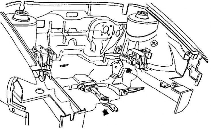
View of the engine compartment with elastic pads and longitudinal support installed
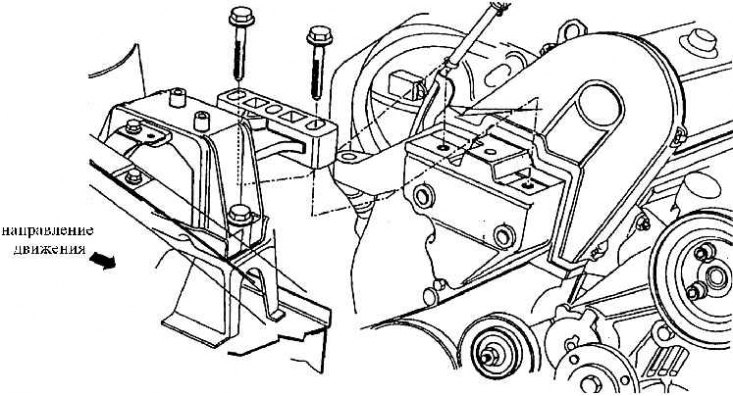
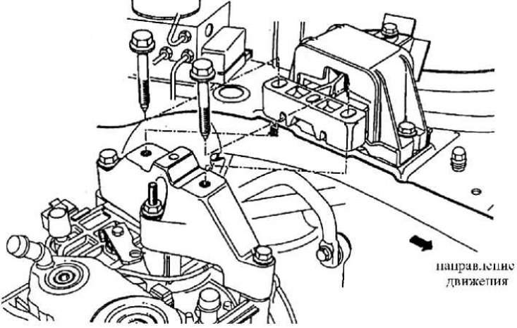
Console on the 1.6-55 kW engine (AEE) and its installation on an elastic lining in the body
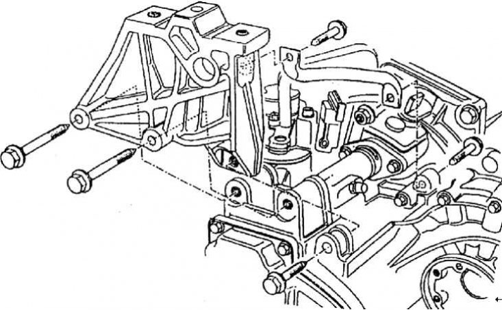
Console on gearbox 02J (CZM, CZL) for landing on console in body
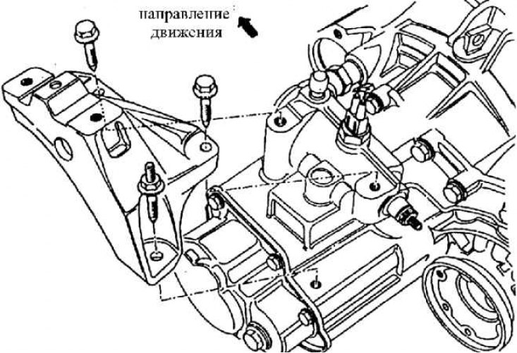
Console on gearbox 02K (CZD, CZE) for landing on console fixed in body
The console on the automatic transmission and its fastening with bolts to the elastic lining fixed to the body
Material is available on the website (www.SkodaBook.ru)
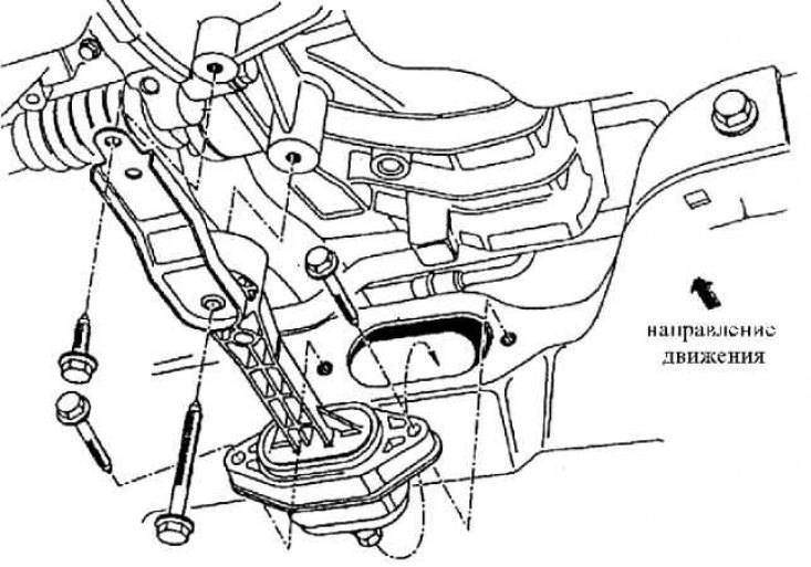
Fastening the reaction support between the drive unit and the front axle
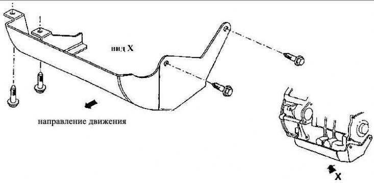
Automatic transmission protective sheet AG 4 (type X)
The drive unit is installed in the body at three points. In two places it is suspended on elastic pads, the third element is an elastically installed reactive support oriented coaxially with the longitudinal axis of the transport device.
The principle of mounting drive units in the body of all combinations of engines with gearboxes is conceptually unchanged. The difference is observed only in the details of the shape of the fastening elements, brackets and in the rigidity of the spring elements. The fastening elements are similar in all types and modifications of cars and all used drive units.
One elastic lining is on the engine side, the second one is on the gearbox side. Each of them is fastened with screws to the body seats on one side (in the engine compartment), and on the other hand, either to the engine or to the gearbox. The spacers allow the drive unit to move in the longitudinal and transverse directions. The longitudinal support consists of two parts and is fastened with two screws at the rear to the axle beam of the front suspension and at the front with two more screws from below to the drive unit. In a calm state, there are no stresses in the support, but during operation, longitudinal forces and movements occur that act between the drive unit and the body. The dimensional changes of the support act identically in the longitudinal direction, the technical parameters of the spring parts change according to the combinations of engines and gearboxes used.
In Fig. View of the engine compartment with installed elastic pads and longitudinal support the engine compartment with installed elastic pads is shown. In Fig. Console on the 1.6–55 kW engine (AEE) and its installation on an elastic pad in the body, Fig. Console on the 02J gearbox (CZM, CZL) for landing on the console in the body, Fig. Console on the 02K gearbox (CZD, CZE) for landing on the console secured in the body, Fig. Console on the automatic transmission and its fastening with bolts to the elastic pad secured to the body, Fig. Fastening of the reaction support between the drive unit and the front axle examples of the structural arrangement of elastic pads and their fasteners are given. In Fig. Protective sheet of the AG 4 automatic transmission (view X) the protective sheet is shown, which is installed only when using an automatic transmission. The specified design solution for installing the unit limits the transmission of sound and vibration from the drive unit to the body to a minimum. The connection between the units in the body and the drive is provided only by wires, hoses and cables. All drive units are installed in the body on a preliminary assembly exclusively from below, using a special auxiliary frame on lifting and transport equipment.