
Scheme of sensors and active elements
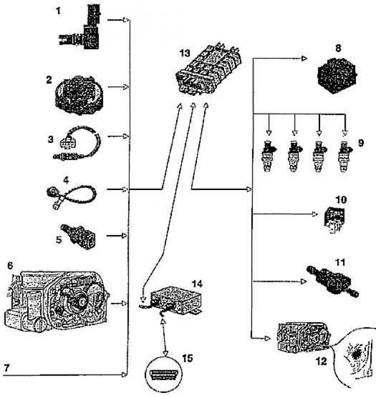
Sensors: 1 - combined intake air pressure sensor (G 70) and its temperature (G 72); 2 - ignition distributor with Hall sensor; 3 - lambda probe (G 39); 4 - knock sensor; 5 - coolant temperature sensor (G 62); 6 - throttle potentiometer (G 69); idle contact (F 60); throttle control (G 88); 7 - incoming signals
Active elements: 8 - ignition coil with a powerful output stage (N 152); 9 - nozzles; 10 - fuel pump relay (J 17); 11 - electromagnetic vent valve (N80); 12 - throttle control (V 60); 13 - control unit (J 382); 14 - immobilizer control unit in the dashboard; 15 - diagnostic connector
Hall sensor and its operation
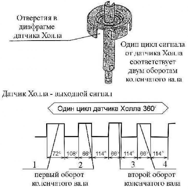
1 – interval for cylinder 1; 2 – interval for cylinder 3; 3 – interval for cylinder 4; 4 - interval for cylinder 2
The Hall sensor is installed in the ignition distributor, which, as already mentioned, is connected to the camshaft. Sensor power (voltage 5v) submitted through the WU. The Hall sensor determines the top dead center of all four cylinders. The signal is generated from four holes in the diaphragm mounted on the ignition distributor shaft (the number of holes corresponds to the number of cylinders). The hole for the first cylinder is larger than the other three. During engine operation (about 7 seconds after the start) the hole for the first cylinder is statistically estimated and thus the ignition moment in the first cylinder is set and the ignition moments for the remaining three cylinders are determined and the system switches from synchronous injection to sequential injection.
The information from the Hall sensor is the basis for calculating the ignition timing, the start of injection and its volume. The ignition timing for the engine start mode is fixed at 6 before top dead center. The signal from the ignition distributor is the only information about the angle of rotation (installations) crankshaft.