



Nozzle in the suction line
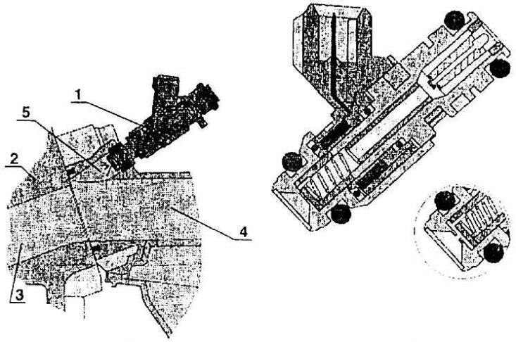
1 – nozzle; 2 – cylinder head; 3 – suction channel in the cylinder head; 4 – suction channel in the pipeline; 5 – fuel injection
Throttle control unit
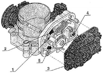
1 – sliding contact; 2 – throttle potentiometer; 3 – unit casing; 4 – throttle positioner motor; 5 – setpoint potentiometer
The difference between the special shape of the intake throat of the 1.6-55 kW engine and the 1.8-92 kW engine and the cylindrical shape
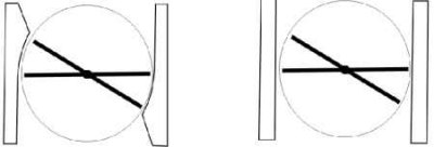
picture on the left: special shape (spherical surface – calotte);
picture on the right: cylindrical shape
Fuel injection is an integral part of the MPI system and consists of:
- injection distributor strips with injectors;
- pressure regulator;
- throttle control unit.
Injection distributor bar
The injection distributor plate forms a mounting kit with the injectors, installed on the intake manifold. The injectors are arranged in a row on the plate and are sealed on the intake manifold using rubber washers. When installing the intake manifold on the cylinder head, it is necessary to ensure that neither the seal nor the seating surface are damaged. The tightening torque of all eight fastening bolts must be the same (M – 20 Nm). The injectors are controlled by pulses using electromagnets of the control unit. Fuel is injected into the intake channel and, together with air, enters the combustion chamber of the corresponding cylinder (see fig. Nozzle in the suction line).
Fuel pressure regulator
The fuel pressure regulator is installed on the left side of the distributor bar. The regulator maintains a constant difference between the pressure in the intake manifold and the fuel pressure. Thus, a change in the pressure in the intake manifold does not affect the amount of fuel injected. When the engine is turned off, the regulator closes the fuel flow back to the tank and thus maintains the fuel pressure in the system. The pressure regulator is installed during preliminary assembly and its parameters cannot be changed.
Throttle control unit
The task of the node (see fig. Throttle control unit) is to stabilize the engine operation at idle speed under various conditions and loads. The adjustment is carried out by the control unit. The sliding contact, throttle valve potentiometer and throttle valve setter potentiometer inform the control unit about changes in the position of the throttle valve and ignition distributor.
To adjust the throttle valve at idle speed, a throttle valve actuator controlled by the control unit is used.
The idle speed control unit must not be opened or mechanically tampered with. Installation can only be done at a Skoda service center using the VAG 1552 tester.
The air flow in the throttle valve is shown in Fig. The difference between the special shape of the intake throat of the 1.6-55 kW engine and the 1.8-92 kW engine and the cylindrical shape. The special shape of the intake throat allows for the finest adjustment of the amount of air at idle speed, as well as a very fine response to the gas pedal.