



Ignition
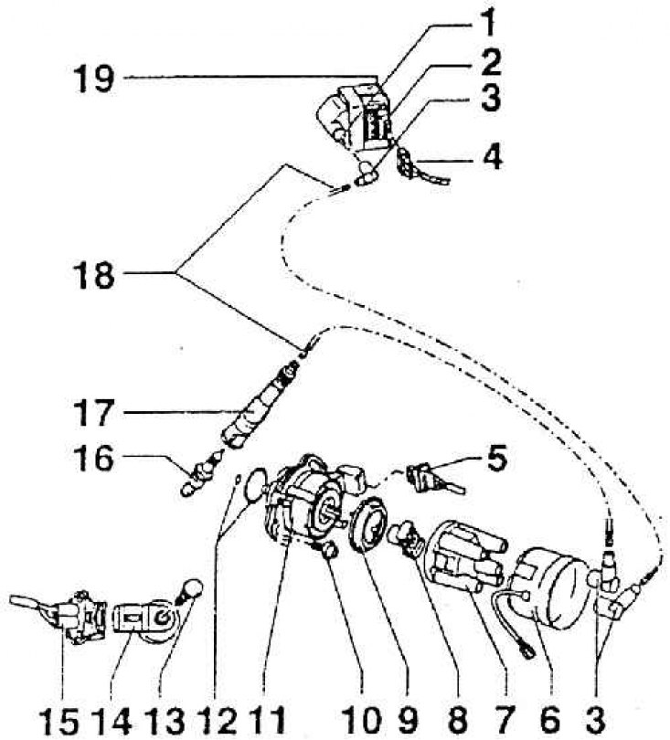
1 – ignition module (N 152); 2 – output stage of the high-power ignition module – ignition coil (N 157); 3 – resistor (from 0.6 to 1.4 kOhm); 4 – connector; 5 – three-pin Hall sensor connector; 6 – shielding cover; 7 – distributor cap; 8 – distributor slider; 9 – Dustproof seal; 10 – Allen bolt (M= 65 Nm); 11 – distributor with Hall sensor; 12 – washer: 13 – bolt (M = 20 Nm; M affects the function of the knock sensor); 14 – knock sensor G 61); 15 – two-pin knock sensor connector; 16 – spark plug (M = 25 Nm); 17 – spark plug connector (from 4 to 6 kOhm); 18 – high-voltage ignition wire; 19 – bracket
Electronic ignition consists of:
- control unit 1 AV, calculating the angle of connection, ignition timing;
- distributor with Hall sensor;
- ignition module;
- high voltage ignition wires;
- spark plugs;
- details associated with them.
For the ignition control system, the input information consists of basic and corrective information.
Basic information
- engine speed;
- amount of incoming air;
- pressure and temperature of incoming air.
Corrective information
- detonation signal;
- incoming air temperature;
- coolant temperature;
- signal from throttle potentiometer;
- supply voltage from the battery.
Functions of the ignition system
- ignition timing adjustment;
- ignition angle calculation;
- idle speed stabilization;
- selective detonation control.
The ignition timing is calculated based on the characteristics stored in the control unit memory. When starting the engine, a rigidly set ignition timing is used. The transition to normal operation occurs as soon as the first cylinder, as well as the three remaining ones, are recognized by the Hall sensor and coordinated accordingly.