
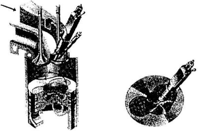
Direct fuel injection and injector detailing
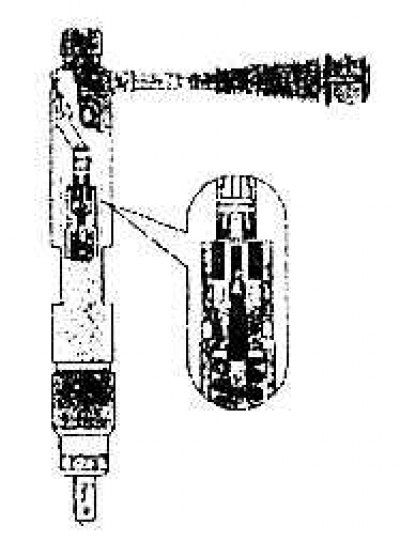
The scheme of the nozzles
Overview of electronic control systems for sensors, sensing elements and switches
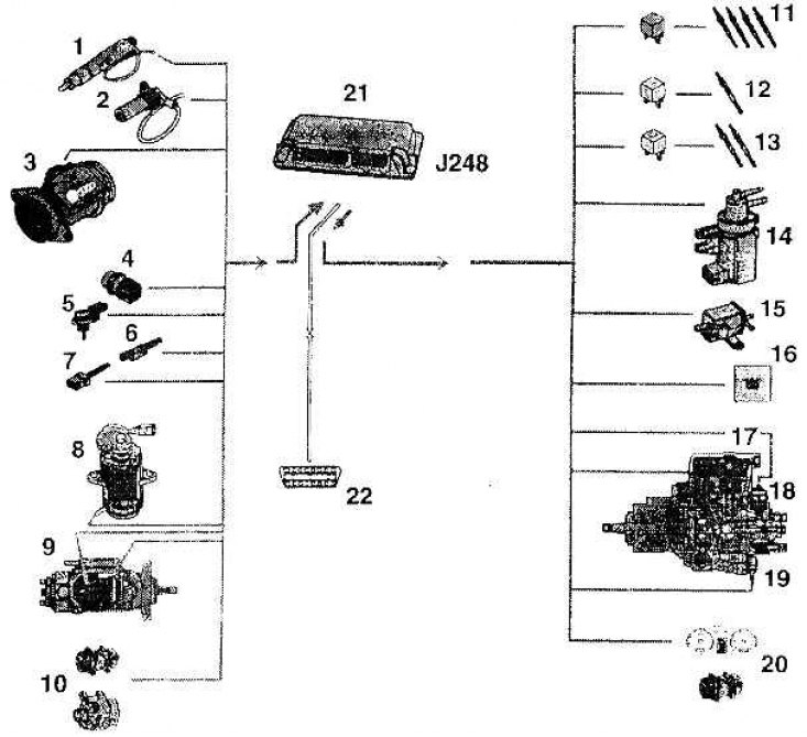
1 - needle movement sensor (G 80); 2 - engine speed sensor (G 28); 3 - sensor for the amount of sucked air (G 70); 4 - coolant temperature sensor (G 62); 5 - temperature sensor in the suction pipe (G 72); 6 - brake light switch and brake pedal switch (F 47); 7 - clutch pedal switch (F 36); 8 - gas pedal position sensor (G 79); 9 - control valve trajectory sensor (G 149); 10 - additional signals: air conditioner and terminal + DF of the generator; 11 - engine glow plugs (Q 6) and glow plug relay (J 52); 12 - candles for heating the coolant (Q 7) and heating relay N of scarlet power (J 359); 13 - candles for heating the coolant (Q 7) and high power heating relay (J 360); 14 - solenoid valve for exhaust gas return (N 18); 15 - solenoid valve boost pressure limitation (N 75); 16 - control lamp for the duration of pre-calcination, control lamp (K 29); 17 - fuel quantity regulator; 18 - fuel shut-off valve (N 109); 19 - injection start valve (N 108); 20 - additional signals: engine speed signal, fuel consumption signal, air conditioner operation signal; 21 - direct fuel injection control unit (J 248); 22 - diagnostic connector
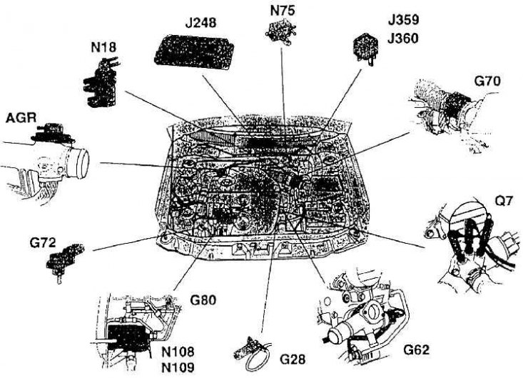
Placement of electronic controls in the engine compartment
Bracket Mounted Engine Accessories
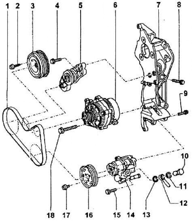
1 - multi-ribbed belt; 2 – a bolt of fastening of a pulley; 3 - crankshaft pulley for a multi-ribbed belt; 4 – a bolt of fastening of the case of the tension device of a belt drive; 5 - belt drive tensioner; 6 - generator; 7 - bracket; 8 - bracket mounting bolt (M = 45 Nm); 9 – a bolt of fastening of the pump of the amplifier of a wheel (M = 25 Nm); 10 - flow bolt (M = 30 Nm); 11 - sealing washer; 12 - eye of the pipeline; 13 - sealing washer; 14 - vane oil pump for power steering; 15 - bolt; 16 - pulley; 17 – a bolt of fastening of a pulley; 18 – a bolt of fastening of the generator
Multi-ribbed belt trajectory
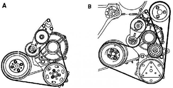
A - belt trajectory in cars without air conditioning;
B - belt trajectory in cars with air conditioning
As already mentioned, the 1.9 TDI-66 kW engine has direct fuel injection, into a chamber formed in the piston (see fig. Direct fuel injection and injector detailing (sectional view)). The following figure, Injector Schematic, shows the details of the injectors and how they work.
Nozzles with five holes (hole diameter 0.17 mm) are screwed into the cylinder head and connected with steel pipes to the piston fuel pump. The pump is driven by a timing belt along with timing gears and a coolant pump.
Control node
The control of all functions given in the overview of systems of electronic elements is carried out by the control unit by means of switches, namely on the basis of signals and information from sensors and sensing elements, depending on the program and the will of the driver. An overview of the engine controls is shown in fig. An overview of the systems of electronic controls for sensors, sensing elements and switches, and their approximate location is shown in fig. Placement of electronic controls in the engine compartment. The system has a self-learning adaptive control program; there is also a diagnostic program and, consequently, a terminal block for connecting diagnostic equipment.
The engine assembly also includes the following assemblies:
The coolant pump, located in the cavity of the crankcase on the side of the timing gears, is driven by a toothed belt drive together with the timing gears. The pump is a compact mounting unit and in case of damage it is completely replaced in the service. Turbine pump impeller. It is attached to the crankcase of the engine with a flange, which is part of the pump, screwed into the threaded holes in the block with two M8 bolts, which simultaneously fasten the protective cover behind the toothed belt drive of the pump drive. The pump is sealed to the block with a rubber washer. The pump bearings are grease lubricated.
Accessory bracket (see fig. Bracket Mounted Engine Accessories) located on the left side of the engine (on the front side in the direction of travel). On the bracket are fixed: fuel pump, generator, power steering pump, belt tensioner, as well as the air conditioning pump. The pulleys of these units are driven by a multi-ribbed belt. Its trajectory is shown in Fig. Multi-ribbed belt trajectory; A - version without air conditioning, B - version with air conditioning.