



Engine block-crankcase with crankshaft and flywheel
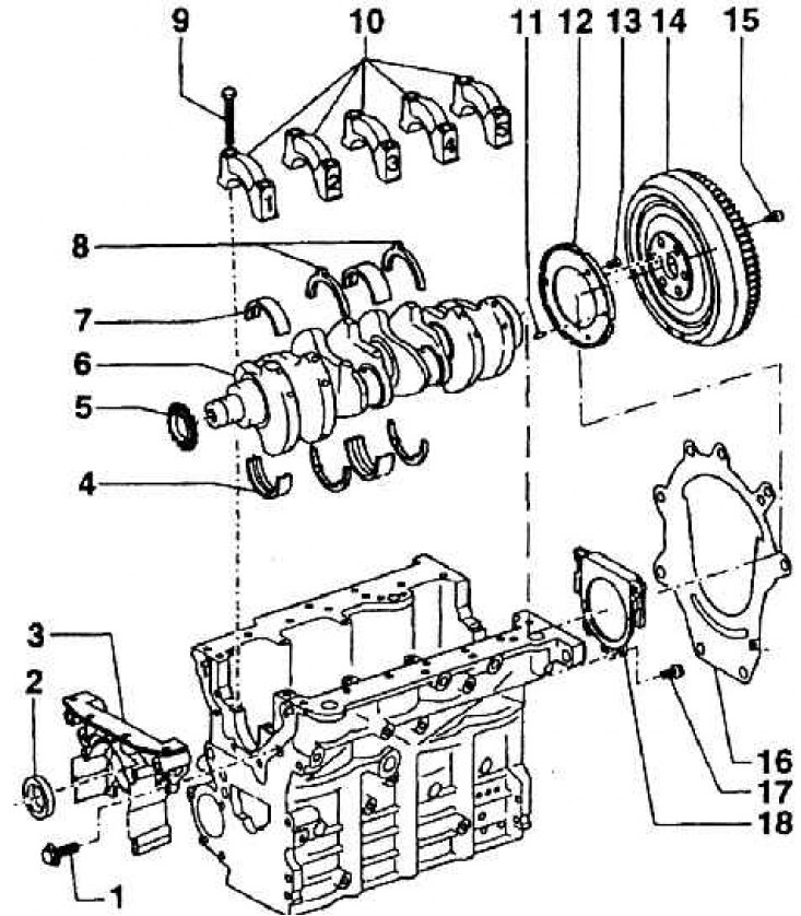
1 – bolt for fastening the front sealing cover of the block (M = 15 Nm); 2 – sealing washer gufero; 3 – front sealing cover; 4 – bearing shells in the block; 5 – oil pump drive sprocket; 6 – crankshaft; 7 – bearing shells in covers; 8 – guide rings for selecting the axial clearance of the crankshaft; 9 – main bearing cap bolts; 10 – crankshaft main bearing caps; 11 – centering pins; 12 – wheel with slot for speed sensor; 13 – wheel mounting bolt; 14 – flywheel with cage; 15 – bolt; 16 – gasket between the engine block and gearbox; 17 – rear sealing cover mounting bolt; 18 – rear sealing cover with gufero washer
The engine block-crankcase is cast from gray cast iron with already formed cylinder liners. The crankshaft bearings have cast iron covers, which are part of the block, including bolts. Both halves of the bearings contain inserts made of steel sheet with an aluminum working friction surface. The inserts have tongue locks and lubrication grooves along the central circumference.
The bearing caps are all the same, the liners are similar for bearings 1, 2, 4, 5. The third bearing has a different liner because during assembly, the axial clearance is selected using side guide rings.