
Removing and installing engine control unit -J623- (without protective housing)
Switch on the ignition and select Tester. Press the following buttons in turn on the display: 01 - Engine electronics, 01 - Guided functions, 01 - Basic setting, 01 - Replacing the engine control unit. Switch off the ignition and remove the ignition key from the lock.
Note: Several variants of brackets for engine control unit -J623- were installed during production. The order of operations for removal and installation remains unchanged.
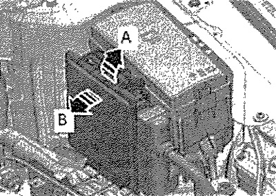
Move lock in -direction of arrow A- and remove control unit -arrow B-. Unlock and disconnect connectors for engine control unit -J623-.
Installation
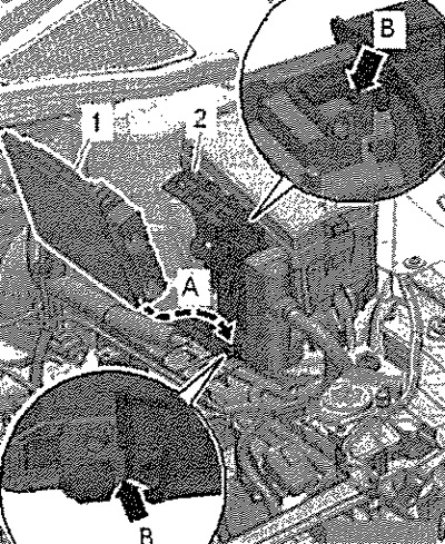
Install engine control unit bottom edge first -arrow A-. The jumpers on the engine control unit -J623- must fit into the upper and lower recesses -arrow B-.
After installing the engine control unit, the following work must be performed. Operate engine control unit -J623- as follows: switch on ignition and select tester. Press the following buttons in turn on the display: 01 - Engine electronics, 01 - Guided functions, 01 - Basic setting, 01 - Replacing the engine control unit.
Removing and installing engine control unit -J623- (with protective housing)
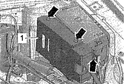
Switch on the ignition and select Tester. Press the following buttons in turn on the display: 01 - Engine electronics, 01 - Guided functions, 01 - Basic setting, 01 - Replacing the engine control unit. Switch off the ignition and remove the ignition key from the lock. Unscrew shear bolts -arrows- for removing protective housing -1- as follows.
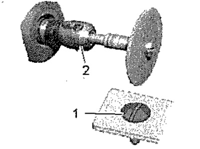
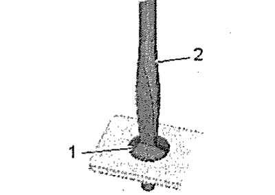
Cut through the head of the shear bolt -1- with a screwdriver slot -2-.
Note: The threads of the shear bolts are coated with threadlocker. Heating the shear bolt when grinding the slot for a screwdriver makes it easier to unscrew it. If shear bolts do not come out, heat them up with a heat gun.
Heating shear bolts with an industrial hair dryer
Set the temperature setting potentiometer -2- to maximum heat output and the air volume on/off switch -3- to position 3.
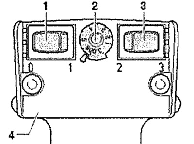
Heat the head of the shear bolt -1- for approx. 20-30 seconds.

Further with loose bolts
Unscrew shear bolt -1- with screwdriver -2-.
Carefully! Do not allow the engine control unit to come into contact with the positive battery terminal - risk of damage. Several variants of brackets for engine control unit -J623- were installed during production. The order of operations for removal and installation remains unchanged.
Move lock in -direction of arrow A- and remove control unit -arrow B-. Unlock and disconnect connectors for engine control unit -J623-.
Installation
Installation in reverse order. Install engine control unit bottom edge forwards -arrow A-. Jumpers on engine control unit -J623- must fit into upper and lower recesses -arrow B-. Always close the engine control unit -J623- with protective cover again. Clean the threaded holes for the new shear bolts to remove any remaining threadlocker. You can clean the thread with a tap. Use new shear screws when installing. After installing the engine control unit, the following work must be performed. Operate engine control unit -J623- as follows: switch on ignition and select tester. Press the following buttons in turn on the display: 01 - Engine electronics, 01 - Guided functions, 01 - Basic setting, 01 - Replacing the engine control unit.