
Note: After replacing the fuel rail, the intake duct flap potentiometer -G336- must be adapted to the engine control unit -J623-.
Remove engine cover. Remove screws -arrows- securing coolant pipe to intake manifold. Remove the air filter housing.
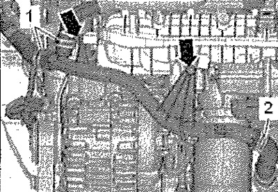
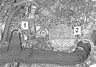
Unscrew left and right screws -arrow-. Detach bottom part of air duct -1- from mountings and remove. Remove soundproof cover.
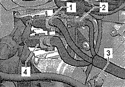
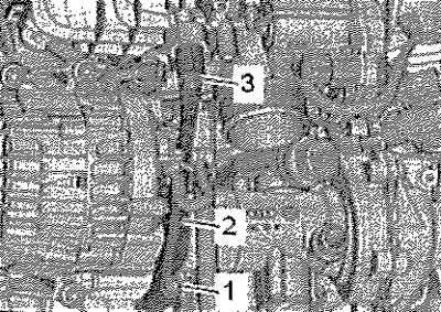
Release coolant hose -3-. Unplug connector -1- at charge pressure sender -G31-. Remove screws -arrows-. Loosen clamp -2- on air hose and remove air hose from throttle valve unit -J338- towards bottom.

Disconnect the following connectors.
1. From FSI injectors
2. From knock sensor 1-G61-
4. From intake manifold flap valve -N316-, fuel pressure sender G247-, intake manifold flap potentiometer -G336-, coolant temperature sender -G62-, Hall sender -G40-
Attention! The fuel system is under pressure! Before opening the high pressure circuit of the injection system, the fuel pressure must be reduced to residual pressure.
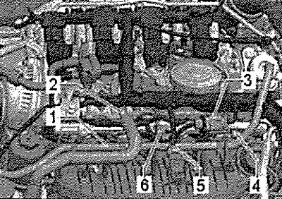
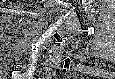
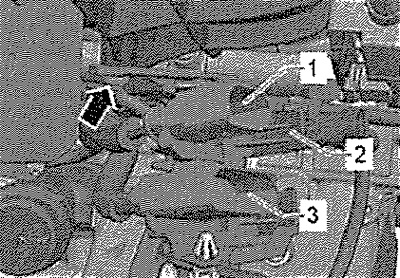
Detach fuel supply line -1- from intake manifold. Remove connector -3- from bracket. Disconnect connectors -4, 5 and 6-. Disconnect the wiring harness from the fuel rail.
Unplug connector from intake manifold flap valve -N316- -2-. Disconnect vacuum lines -arrows-6t from intake manifold flap valve -N316- -2- and from air cleaner housing.
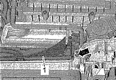
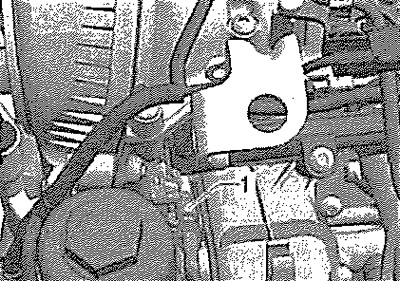
Remove screw -1- and press air duct to the left.
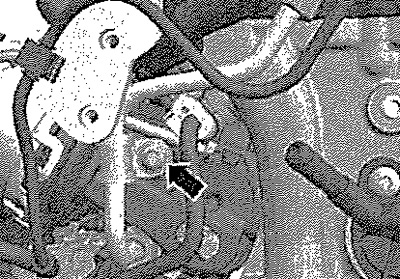
Unscrew retaining clip -arrow- for high-pressure fuel line. Loosen the union nuts of the high pressure fuel line at the high pressure pump and at the fuel rail. Remove the high pressure pipe.
Note: The fuel system must not be pressurized. Collect escaping fuel with a clean cloth. Close open fittings with clean protective caps. Make sure that no dirt gets into the fuel system.
Slightly loosen the fastening nut -3- and unscrew the screw -1- completely.
Disconnect connector -1- from intake manifold flap potentiometer -G336-. Remove intake manifold screws.
Pull intake manifold slightly off cylinder head and unscrew connector bracket -arrow-.
Note: Close the inlets with a clean cloth.
Installation
Screw the connector bracket back. Slide the intake manifold over the threaded studs (bottom left and right) on the cylinder head. Installation in reverse order.