Note. Minor leaks can be detected, for example, with an electronic detector.
1. Evacuate the refrigerant circuit using an air conditioner service stand.
Note.
- If a relatively large leak is already detected during evacuation, the leak must be found and repaired.
- If no leak is found during evacuation, or if the leak is so small that it is not possible to locate the leak, proceed as follows.
- The gaseous refrigerant is rapidly carried away by the air currents. Therefore, when looking for a leak, avoid drafts.
- If the circulation circuit is completely empty, fill it with refrigerant to approx. 10% of the filling capacity (see sticker R134a or workshop manual for the respective vehicle).
Note.
- Necessary equipment:
- Leak detection kit -VAS 6196- or
- Leak detection kit -VMS 6201-.
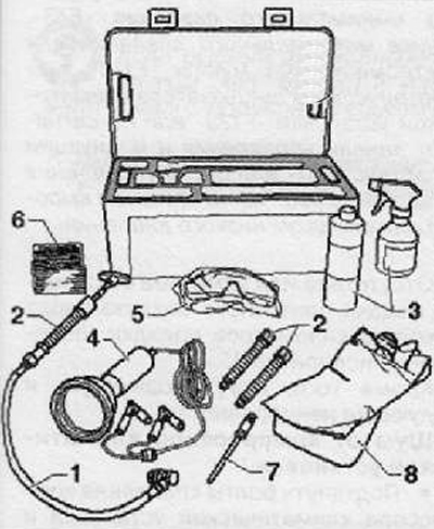
1 - Hand pump with low-pressure service hose, service connector and non-return valve VMS 6201/1-
2 - Cartridge -UAS 6201/2-
3 - Cleaning agent -VAS 6201/3-
4 - UV leak detection lamp -VMS6201/4-
5 - UV protection goggles -VAS 6201/6-
6 - Stickers -VAS 6201/7-
7 - TpyOxaVAS 6201/8
8 - Protective gloves -VAS 6201/9-
Introducing a leak detecting additive into an empty refrigerant circuit
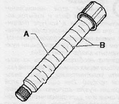
Cartridge -A- contains 15.4 ml of leak detection additive (one division -B-scale corresponds to 2.5 ml).
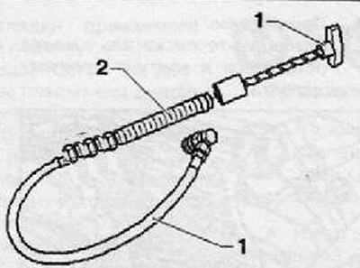
1. Assemble hand pump -VAS 6201- (pos. -1-) with cartridge (pos. -2-) -VAS 6201/2-.
2. Insert filling tube -VAS 6201/8- into hand pump (pos. -7-).
3. Open the service valve of the hand pump.
Note. The leak detection additive is optimally introduced into the empty refrigerant circuit via an open connection.
4. Open the refrigerant circuit in a well-accessible connector area.
5. Cover the area around the connector with cling film or absorbent paper.
6. Keep the tube upside down.
7. Screw in the hand pump knob until the leak detection additive begins to come out of the tube.
8. Inject 2.5±0.5 ml (ml = cm3) leak detection additives in the refrigerant circuit.
Note. If a leak detection additive was added to the refrigerant circuit during a previous repair, note the following: Add a new additive if the compressor oil is changed. If only part of the refrigeration oil has been replaced, only the appropriate proportion of the additive should be added. For example, if a car with 250 ml of refrigerant oil has been replaced with 100 ml of this oil, only 1 ml should be added (cm3) leak detector additives.
9. Replace the O-rings in the exposed areas of the connector.
10. Assemble the refrigerant circuit
11. Affix a sticker next to the service fittings to warn that a leak detection additive has been added to this refrigerant circuit.
12. Evacuate and charge the refrigerant circuit in accordance with the instructions.
13. Put the air conditioner into operation.
Note. The climate control system must operate for at least 60 minutes so that the introduced leak-detecting additive is distributed throughout the conduit (the compressor must be running). Depending on the size of the leak, the leak may already be detected during this time.
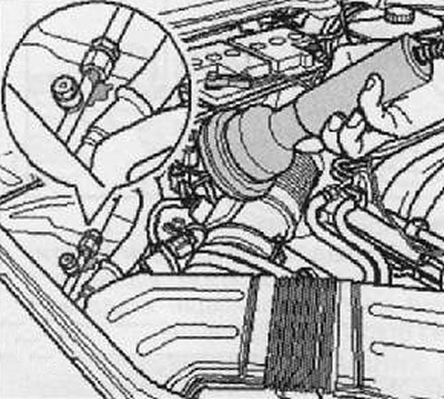
14. Find the leak in the refrigerant circuit using the UV lamp VAS 6196/4.
Adding a leak detecting additive to a charged refrigerant circuit
Note.
- If a leak detection additive was added to the refrigerant circuit during a previous repair, note the following: Add a new additive if the compressor oil is changed. If only part of the refrigerant oil has been changed, only the appropriate proportion of the additive should be added. For example, if 100 ml of this oil was changed on a car with 250 ml of refrigerant oil, only 1 ml should be added (cm3) leak detector additives.
- A small amount of leak detector additive remains in the service fitting. Carefully remove these residues so that they are not mistaken for leaks when subsequently looking for a leak.
- Cartridge -A- contains 15.4 ml of leak detection additive (one division -B-scale corresponds to 2.5 ml).
1. Turn off the ignition.
2. Remove the plug from the service port on the low pressure side of the refrigerant circuit.
3. Assemble hand pump -VAS 6201- (pos. -1-) with cartridge (pos. -2-) -VAS 6201/2-.
Note. Make sure the hand pump hose is completely filled with leak detection additive.
4. Install the quick coupling on the low side service port and open the service coupling by screwing in the handwheel. While holding the hose end up, screw in the hand pump knob until the leak-detecting additive begins to come out of the tube.
5. Cover the area around the service port on the vehicle with foil or absorbent paper.
6. Turning the knob of the hand pump, inject 2.5±0.5 ml (ml = cm3) leak detection additives in the refrigerant circuit.
7. Close the service sleeve and remove it from the service port.
8. Remove the remnants of the leaking agent from the service port, for example, with absorbent paper.
9. Close the service port with a plug.
10. If necessary, clean the area around the service port with a cleaning agent.
11. Affix a sticker next to the service fittings to warn that a leak-tight additive has been added to this refrigerant circuit.
12. Put the air conditioner into operation.
Note. The air conditioning system must operate for at least 60 minutes so that the introduced additive-leak-scaling agent is distributed throughout the circuit (the compressor must be running). Depending on the size of the leak, the leak may already be detected during this time.
13. Find the leak in the refrigerant circuit using the UV lamp VAS 6196/4.
Finding leaks in the refrigerant circuit with the UV lamp VAS 6196/4
Attention.
- Do not look into the UV lamp.
- Do not point the UV lamp at other people.
Note.
- The air conditioning system must operate for at least 60 minutes so that the introduced leak detector additive is distributed throughout the circuit (the compressor must be running). Depending on the size of the leak, the leak may already be detected during this time.
- If the evaporator leaks, the additive can be washed out by condensate and drunk through the drain hose. Since the evaporator is not available on most vehicles without laborious preliminary work, its tightness can be judged, for example, by a test on the drain hose. But for this, it is necessary that the additive has been in the refrigerant circuit for a long time.
- Goggles not only protect the eyes, but also enhance the luminescence of the additive under UV rays.
- Depending on the accessibility of various components of the refrigerant circuit, it may be necessary to remove some components of the vehicle (e.g. bumper or air filter).
1. Move the car to a darker place in the service station (in daylight or strong light, the effect of UV rays is weakened).
2. Check the availability of access to various components of the refrigerant circuit and remove adjacent parts obscuring these components (e.g. acoustic covers and bumper).
3. Wear safety goggles.
4. Connect the UV lamp to a 12V power supply (car battery). When doing so, observe the correct polarity of the terminals.
5. Turn on the UV lamp and illuminate the components of the refrigerant circuit. Places where, due to leaks, refrigerant, refrigerant oil, and with them a leak-detecting additive, ooze under UV rays (fluoresce).
Note. The leak detecting additive may remain in the refrigerant circuit.