



Contents: Removal ⬇ Installation ⬇
Removal
Note.
- All wire connections that were loosened or disconnected during removal must be re-fastened in their original location upon reinstallation.
- After disconnecting and then connecting the wire connecting the battery terminal to the ground (body) of the vehicle, some additional work must be performed.
1. The wire connecting the battery terminal to the ground (body) of the vehicle should be disconnected with the ignition off.
2. Remove the upper decorative engine cover.
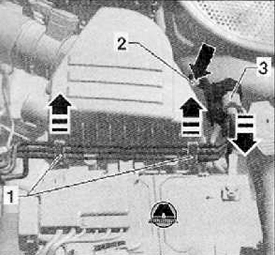
3. Remove the vacuum wires with the holder (1) from the air cleaner and disconnect the wiring harness connector (3) by pulling it in the direction of the arrow as shown in the figure below.
4. Unscrew the electromagnetic valve for limiting the boost pressure "N75" with the holder (2) "arrow", place it with the vacuum line on the engine.
5. Remove the complete air filter with the air hose.
6. Remove the battery and battery holder (see the relevant section in Chapter Engine electrical equipment).
7. Remove the waterproof casing cover and the front body wall separating the engine compartment from the passenger compartment.
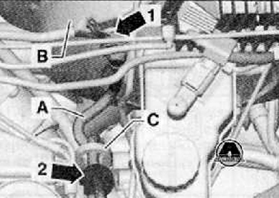
Note: To avoid damaging the intake hose (A) leading from the brake booster (B) to the engine, it must be removed from the brake booster (arrow 1) as shown in the figure below.
8. Remove the rubber support (arrow 2) of the intake hose from the eye (C) on the engine, as shown in the figure below.
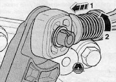
9. After tightening the locking mechanism of the Bowden cable drive of the selective gear shift control device forward in the direction of arrow 1 until it stops, then fix it by turning it to the left in the direction of arrow 2, as shown in the figure below.
10. Remove the retaining clip (arrow 1), shown in the figure below, from the hole in the preselector lever.
11. Remove the selector lever from its support in the gearshift cover together with the Bowden cable locking device.
Note: On some vehicles, the selector lever guide is locked with a lock.
12. Remove the shift cable retaining ring (arrow 2) from the shift lever (A) as shown in the figure below.
13. Remove the gear shift cable from the journal.
14. Remove the gear shift lever (A) by unscrewing the nut (arrow 3), as shown in the figure below.

15. Remove the flexible roller counter support (bowden cables) from the gearbox (arrows), tie it together with the gear shift cable and the cable drive for the preselective control device for shifting gears upwards.
16. After removing the bracket (B) from the gearbox, if equipped, remove it from the pipe and hose line (A) as shown in the figure below.
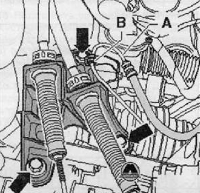
17. Remove the clutch release drive slave cylinder (arrows), set it aside and secure it; without disconnecting the hoses.
Caution: Do not press the clutch pedal any further.
18. Remove the upper bolts connecting the engine and gearbox as shown in the figure below.
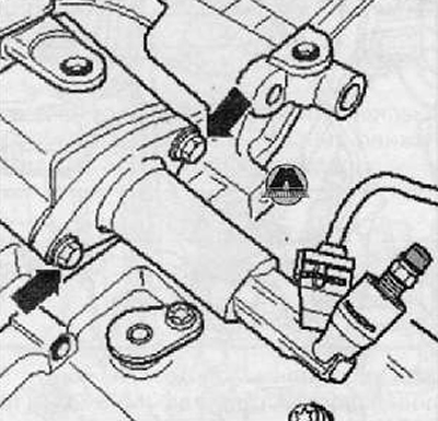
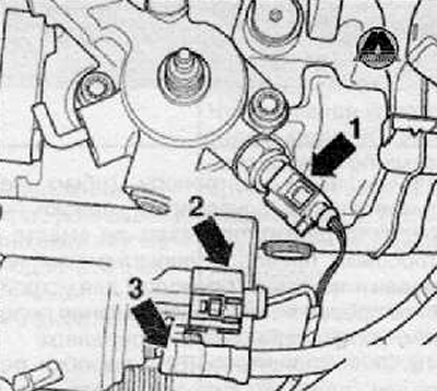
19. Disconnect the plug connector (arrow 1) from the reversing light switch "F4" as shown in the figure below.
20. Disconnect the plug connector (arrow 2) and wire (arrow 3) shown in the figure below from the starter.
21. Leave the disconnected wires lying freely.
22. Remove the upper bolts connecting the engine and gearbox.
23. Remove the upper starter mounting screw.
24. Disconnect the plug connector (arrow) from the speedometer sensor "G22" (if installed), as shown in the figure below.
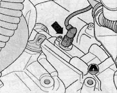
25. After unscrewing the nut (arrow), remove the electrical wire holder.
26. Remove the starter (for more details, see the relevant section in the chapter Engine electrical equipment).
27. Remove the wheel arch (wing) liner of the left front wheel (for more details, see the corresponding section in the chapter Body).
28. Having separated the exhaust pipe at the double clamp, unhook it from the axle suspension mounting beam.

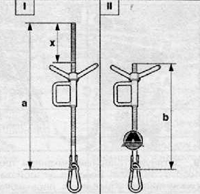
29. The original lead screw (I) of the suspension device (MP9-200 (10-222A)) should be shortened by 100 mm:
- I - Original lead screw
- Size "a" = 442 mm
- Size "x" = 100 mm
- II — shortened lead screw MP9-200/10 (10-222A/10)
- Size "b" = 342 mm
Note: To prevent the original lead screw (I) of the suspension device (MP9-200 (10-222A)) from hitting the engine hood, it is necessary to shorten it by the dimension "x" (100 mm).
30. If there are hose and wire connections near the eye on the engine for the fastening suspension device (MP9-200 (10-222A)) then these connections must now be disassembled.
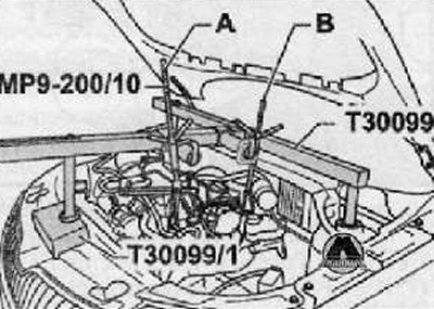
31. Install the suspension device (T30099) with the support beam (T30099/1) as shown in the figure below.
32. Hang the original spindle (A) into the eye on the motor at the front right as shown in the figure below.
33. Place the shortened lead screw (B) onto the "10-222 A/3" adapter shown in the figure below.
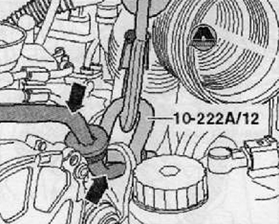
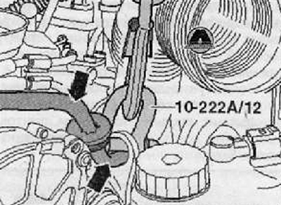
34. Suspension device (10-222 A/12) at the back left it should be hooked into the eye on the engine.
Attention. It is necessary that the suction hose moves freely in the eye (arrows). Avoid damaging it.
35. Then the suspension device should be connected (10-222 A/12) with a shortened lead screw as shown in the figure below
36. Using the lead screws, the engine-gearbox power unit should be slightly pre-tensioned.
37. Remove the protective cover of the front section of the exhaust pipe of the exhaust system.
38. Disconnect the bellows of the front section of the exhaust pipe of the exhaust system.
39. Disconnect and set aside the front section of the exhaust pipe.
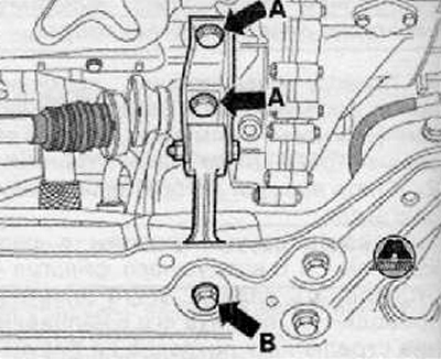
40. Unscrew the mounting bolts and remove the rocker support (arrows A) and (arrow B), as shown in the figure below.
Note: When installing the swing support, it is necessary to place the screws (arrows 1) in the slots so that the gearbox and the suspension mounting beam are as far apart as possible.
41. If present, remove the heat shield for the right drive shaft by unscrewing its mounting bolts (arrows), as shown in the figure below.
42. Turn the steering wheel all the way to the left and remove the drive shafts from the flange shafts.
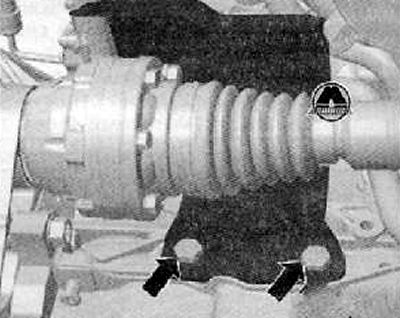
43. Loosen the fastening nuts, shown in the figure below by arrows, of the left ball joint to the lower arm of the front suspension.
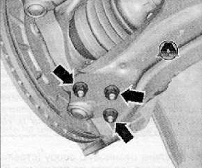
44. Fold the wheel hub bearing housing cover outward to the left.
45. Insert the drive shaft into the wheel well and attach it to the shock absorber strut using a rope. Do not damage the protective paint coating of the drive shaft.
46. The right drive shaft should be secured as high as possible using a rope. In doing so, do not damage the protective paint coating of the drive shaft.
47. Remove the small flywheel protective sheet (A) (arrows), if present, as shown in the figure below.
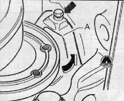
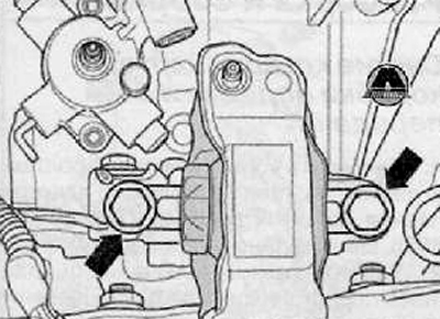
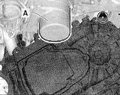
48. Remove the screws (arrows) securing the unit support on the left side from the gearbox bearing, as shown in the figure below.
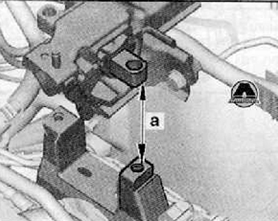
49. The gearbox should be lowered by approximately 55 mm (dimension "a"), as shown in the figure below.
50. In addition, the engine should be lowered a little.
Caution: The suction hose shown by the arrow in the figure below must not be pinched.
Caution: The engine eye must not come into contact with the brake fluid reservoir or brake fluid lines.
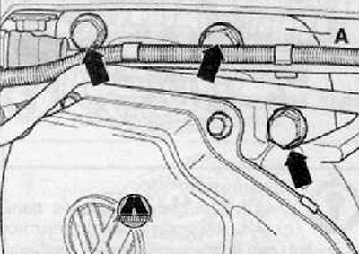
51. Remove the transmission mounting bracket (A) mounting bolts (arrows) as shown in the figure below. Remove the transmission mounting bracket.
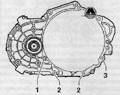
52. Remove the connecting bolt (1) from the engine and gearbox at the bottom.
Note: After loosening the engine and gearbox connecting bolt (3), leave it screwed in so that it can be turned by hand, as shown in the figure below. Bolts (2) and (3) will be removed later.
53. Install the gearbox mounting fixture (3282) into the engine and gearbox removal and installation device, e.g, (VAG 1383 A).
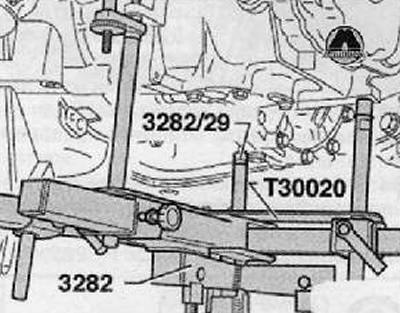
54. Assemble the engine and gearbox removal and installation device with the gearbox mounting device (3282), the alignment plate (T30020) for the "02R" gearbox and the mounting elements as follows:
Place the mounting plate (T30020) on the gearbox mounting fixture (3282) (mounting plate that can be installed in only one position).
Adjust the position of the gearbox mounting device arms to the holes in the mounting plate.
Screw in the fastening elements (A) and (C) according to the marks on the alignment plate.
Screw on the journals (3282/29) as shown on the alignment plate.
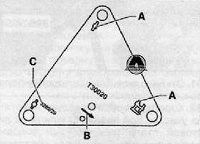
55. Place the engine and gearbox removal and installation device under the vehicle, arrow (symbol B) (in the previous picture) on the alignment plate indicates the direction of vehicle movement.
56. Align the mounting plate parallel to the gearbox and secure the retaining clips.
57. Remove the remaining lower bolts connecting the engine and gearbox.
58. Having disconnected the gearbox from the centering bushings, carefully move it towards the front suspension subframe.
The differential should point upward.
During the removal and installation of the gearbox, the 2nd mechanic presses the engine slightly forward.
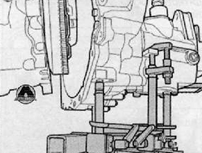
59. Guide the gearbox with differential over the front axle suspension subframe (A) and tilt it back.
60. If necessary, turn the gearbox in the differential section further upwards via the lead screws of the gearbox mounting device (3282).
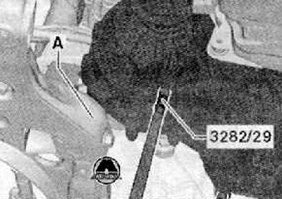
61. Having tilted the gearbox even further, carefully lower it.
62. The gearbox should be lowered in the gear shift section (sheet steel casing) using the lead screws of the gearbox mounting device "3282", as shown in the figure below.
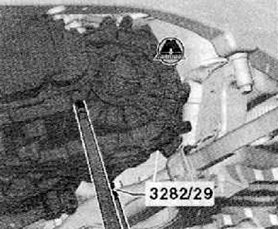
63. The gearbox must not touch the power steering pump (A).
64. During lowering, change the position of the gearbox using the lead screws of the gearbox mounting device (3282).
Note.
- Follow the coolant hose between the engine and the heating system heat exchanger.
- During removal and installation, care should be taken with the engine boost pipe.
- The engine mount bracket must not touch the top of the timing belt guard.
65. Remove the gearbox assembly.
Installation
1. Installation is carried out in the reverse order of removal.
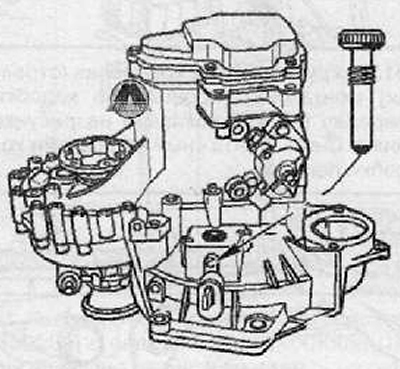
2. Before installing the gearbox, press the clutch release lever against the gearbox housing and secure it with a mounting bolt or an M8x35 bolt.
3. After installing the gearbox, remove the bolt again. The hole is then closed with the third Bowden cable counter support mounting screw.
Note.
- After cleaning the splines of the input shaft, lightly lubricate them with consistent grease for fine-spline connection of clutch discs "G 000 100". The clutch disc on the input shaft should move freely back and forth.
- When installing the gearbox, care must be taken to ensure that the intermediate plate is correctly installed between the engine and the gearbox.
- Check the presence of centering bushings in the cylinder block for centering the gearbox; if necessary, insert them.
- Install the engine support. Assemble the exhaust system without internal stress.
- For vehicles with a particulate filter, the axle suspension mounting beam must be bolted on.
- Install the starter (for more details, see the relevant section in the chapter Engine electrical equipment).
- Install the left wheel arch (wing) liner (for more details, see the relevant section in the Body chapter).
- Install the left front wheel. Install the lower engine cover. Adjust the gearshift drive if necessary.
- Check the transmission oil level. If necessary, add transmission oil to the required level.
- Install a complete air filter with air hose (for more details, see the relevant section in Chapter Intake and exhaust system).
- Install the battery and battery holder (for more details, see the relevant section in Chapter Engine electrical equipment).
- After disconnecting and then connecting the wire connecting the battery terminal to the ground (body) of the vehicle, it is necessary to perform some additional work.