2. Remove the clutch release fork with the clutch release bearing.
Note.
- If the 5th gear is to be reinstalled, then the bearings of the drive and driven shafts must not be damaged.
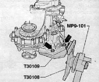
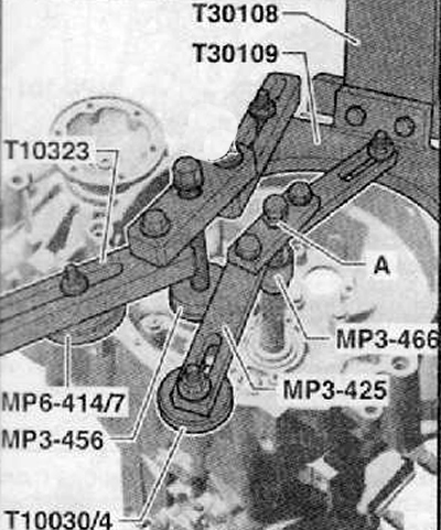
- Therefore, when attaching the gearbox to the fixture (Т30109 (VW 353)), it is necessary to install, for support, the following devices:
- Under drive shaft, puller (MP3-425 (30-211 A)).
- Driving device (MPZ-466 (32-111)).
- pressure piece (Т10030/4).
- Drive shaft, can be supported by driving device (MPZ-466 (32-111)) only later.
- Under the output shaft bearing bracket:
- Puller (Т10323).
- Emphasis -MP6-414/7 (3253/7) - from the assembly tool (MP6-414 3253».
- washer (MPZ-456 (VW 447 i).
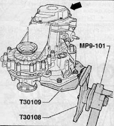
3. Unscrew the mounting bolts and remove the gearbox cover (arrow), shown in the figure below.
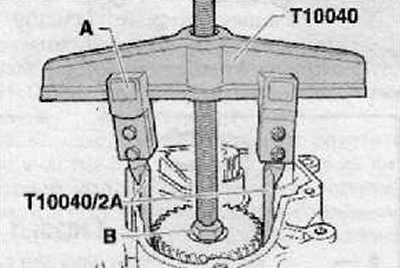
4. Check that the detachable hooks -T10040/2A- can be correctly fitted under the 5th gear, as shown in the figure below.
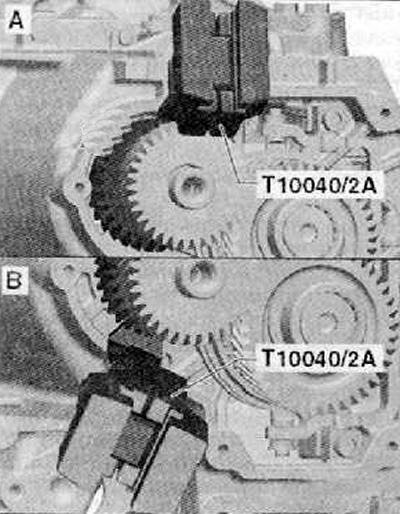
Note. The 5th gear must be removed separately.
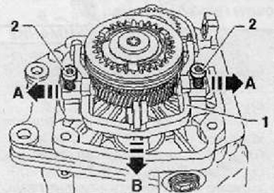
5. The shift fork for engaging 5th gear should be removed as follows:
Openings should be covered with a clean cloth.
Install shift fork (1) to the neutral position as shown in the figure below.
Loosen the fixing screws (2) root neck (neck supports).
Pull out the bearing journals in the direction of arrow A, as shown in the figure below.
Remove the shift fork to engage 5th gear in the direction of the arrow from the sliding sleeve as shown in the figure below.
Note. The 5th gear sliding clutch does not need to be removed.
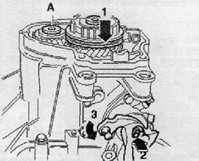
6. Unscrew the fastening bolts (A) synchronizer carriages and 5th gear gears. To do this, you need to turn on the 5th gear (arrow 1) and 1st arrow gear (2) And (3) at the same time, as shown in the figure below. After both gears are engaged, the drive and driven shafts are locked and the carriage and gear cannot turn. At this point, it is possible to loosen both mounting bolts.
Note. If the shafts are not to be changed, the threaded holes must be carefully cleaned from the remains of the fixing agent, e.g. tap.
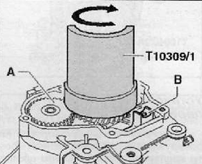
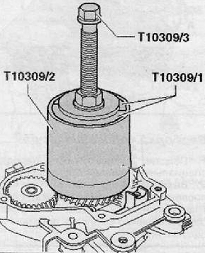
7. Remove the 5th gear synchronizer carriage with sliding sleeve and retainers. Apply puller (Т10309).
Insert the sleeve half first (Т10309/1) between the driven gear of the 5th gear (A) and fastening of a fork of a gear change for inclusion of the 5th gear (IN), as shown in the figure below.
half sleeve (Т10309/1) must be placed under the blocking ring of the synchronizer of the transmission battle.
If necessary, push the sleeve half into its final position.
half sleeve (Т10309/1) should be rotated to the opposite side in the direction of the arrow as shown in the figure below.
A threaded bushing should be inserted into the half of the sleeve (Т10309/3).
Now you should insert the second half of the sleeve (Т10309/1) and a pipe should be installed on the installation tool (Т10309/2), as shown in the figure below.
After removal, check the integrity of the synchronizer carriage.
Replace the 5th gear synchronizer ring.
Remove 5th driven gear with needle bearing.
8. Remove the gear for 5th gear in the following way:
Install the detachable hook first (A), as shown in the figure below.
Note. In the picture below, B is the Screw M 10x20, wrench size 17.
If necessary, heat the gear with a hot air gun (V.A.G 1416).
Note.
- The 5th gear can also be removed with a two-arm puller (Kukko 20/10) combined with detachable hooks (T10040/2A).
- When removing the gear, make sure that the hooks do not slip out. After removal, the integrity of the 5th gear should be checked.