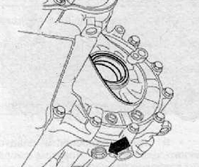
2. Unscrew the oil drain plug (arrow), drain the gear oil into a pre-prepared bath, as shown in the figure below.
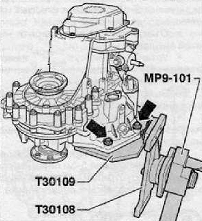
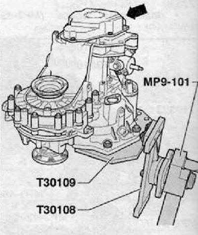
3. Fix the gearbox with bolts (arrows) on the gearbox mount (T30I09 (VW 353)), as shown in the figure below.
4. Remove the clutch release fork, release bearing and guide sleeve.
Attention.
- It is impossible that during the extraction and installation of the 5th gear, the bearings of the drive and driven shafts are damaged.
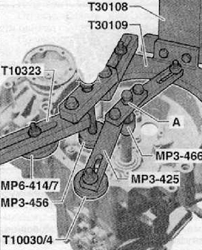
- Therefore, when attaching the gearbox to the gearbox mount (Т30109 (VW353)), it is necessary to install, for support, the following devices:
- Under the drive shaft:
- Puller (MPZ-425 (30-211 A)).
- Driving device (MP3-466 (32-111)).
- pressure piece (Т10030/4).
- Fix the puller screw (MPZ-425 (30-211 A)) nut (A), as shown in the figure below.
- Under the output shaft bearing bracket:
- Puller (Т10323).
- Emphasis (MP6-414/7 (3253/7)) from the assembly tool (MP6-414 (3253)).
- washer (MPZ-456 (VW 447 i)).
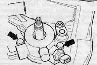
5. Unscrew the mounting bolts and remove the rear cover of the gearbox (arrow), shown in the figure below.
6. The shift fork for engaging 5th gear should be removed as follows:
Install shift fork (1) to the neutral position as shown in the figure below.
Unscrew the fixing screws shown in the figure below (2) root neck (neck supports).
Pull out the bearing journals in the direction of the arrow (A).
Remove the shift fork to engage 5th gear in the direction of the arrow from the sliding sleeve as shown in the figure below.
Note. The 5th gear sliding clutch does not need to be removed.
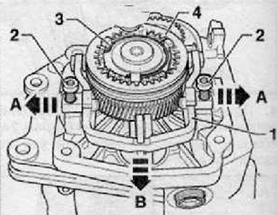
7. Unscrew the fastening bolts (A) synchronizer carriages and 5th gear gears. To do this, you must simultaneously engage the 5th gear (arrow 1) and 1st arrow gear (2) And (3), as shown in the figure below. After both gears are engaged, the drive and driven shafts are locked and the carriage and gear cannot turn. At this point, it is possible to loosen both mounting bolts.
Note. If the shafts are not to be changed, the threaded holes must be carefully cleaned from the remains of the fixing agent, e.g. tap.
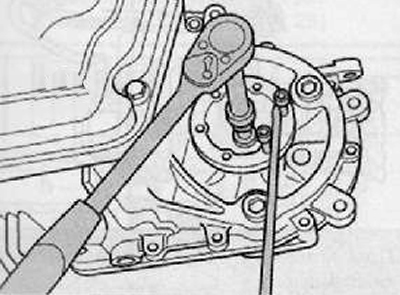
8. Remove both flange shafts. For this purpose, it is necessary to stop the shaft with a flange from turning with a mandrel and unscrew the fastening bolt, as shown in the figure below.
9. Remove flanged shafts with compression springs, guide rings and tapered rings.
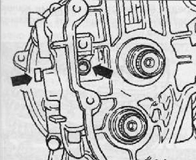
10. Remove both screws (arrows) reverse gear axle bearings as shown in the figure below.
Gearbox for vehicles with Start-Stop system
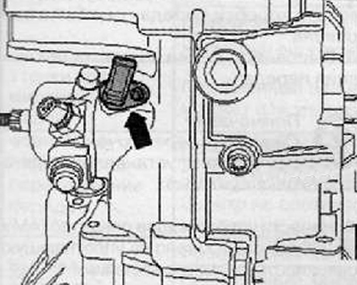
11. Pull out gearbox neutral position sender -G701- (arrow), as shown in the figure below.
12. Remove the shift control shaft with the gear shift cover. Adjust the shift control shaft to the neutral position. Then unscrew the fixing screws (arrows) and remove the shift control shaft from the gearbox housing as shown in the figure below.
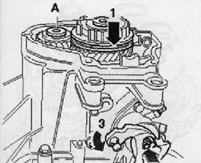
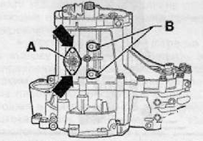
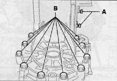
13. Unscrew the fastening screws (arrows) from the lid (A) and remove the bearing (IN) on the underside of the gearbox as shown in the figure below.
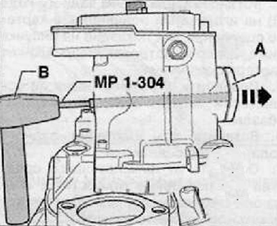
14. Carefully squeeze out the cover (A) using a device for driving valve guides (MP1-304 (10-206)) and hammer (IN), as shown in the figure below.
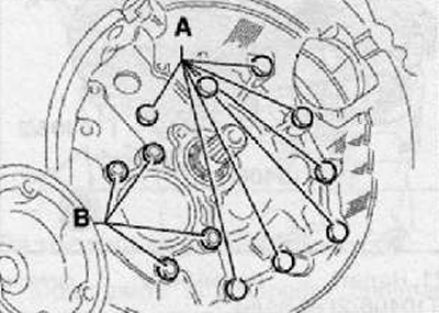
15. Unscrew the fastening screws (A) clutch housing to the transmission housing as shown in the figure below.
Note. Nuts cannot be removed (IN) for fastening the bearing of the driven shaft.
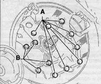
16. Remove bearing journals (A) on the top side of the gearbox and mounting screws (IN), connecting the gearbox housing and clutch housing at the differential section, as shown in the figure below.
17. Remove the following parts together with the gearbox housing;
Synchronizer carriage 5th gear.
5th gear gear.
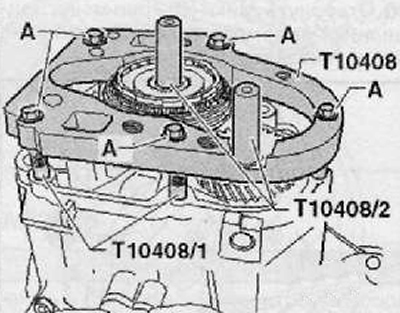
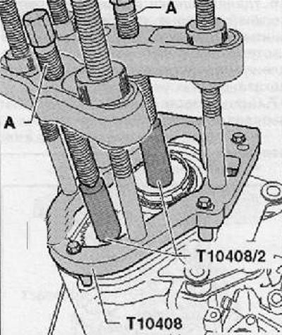
18. Use a special removable plate (Т10408) in combination with the following accessories:
- Spacers (Т10408/1) (5 pieces.).
- Pressure elements (Т10408/2) (2 pcs.).
- Pullers Kukko 18/1 (2 pcs.).
19. Screw in 5 spacers (Т10408/1) into the threaded holes in the gearbox housing cover.
20. Install the removable plate (Т10408) on pressure elements (Т10408/1), as shown in the figure below.
Note. A - M7x35 screws with washers. Tightening torque - 18 Nm.
21. Put on pressure parts (Т10408/2) on the shafts.
22. Install two special pullers (A), For example (Kukko 18/1).
23. Remove the synchronizer carriage for 5th gear, the 6th gear and the gearbox housing by alternately tightening the lead screws (A) (1/2 turn) pullers as shown in the figure below.
Note.
- The 5th gear should, if necessary, be heated with a hot air gun, e.g. -VAG 1416-.
- Check the locking of the needle bearing of the output shaft in the gearbox housing. If the 3 pegs are damaged, this means that the needle bearing has become dislodged during tightening and needs to be replaced.
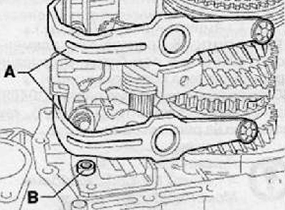
24. Remove shift forks (A) together with the shift fork stems as shown in the figure below.
25. Unscrew the reverse gear engagement mechanism (IN), as shown in the figure below.
26. Loosen the nuts (IN) output shaft bearing as shown in the figure below.
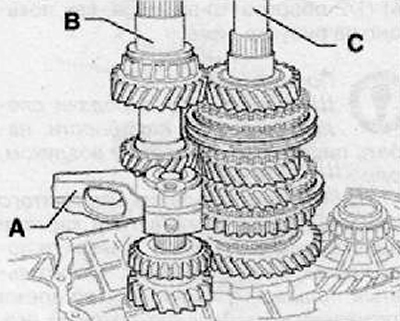
27. Gradually remove the reverse gear from the clutch housing (A), drive shaft (IN) and driven shaft (WITH), as shown in the figure below.
28. Remove differential assembly.