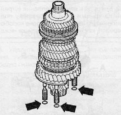
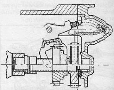
Note. O-rings must always be replaced after disassembly (arrows) bearing bracket of the driven shaft, shown in the figure below.
Note. The illustration shows only three of the four O-rings available.
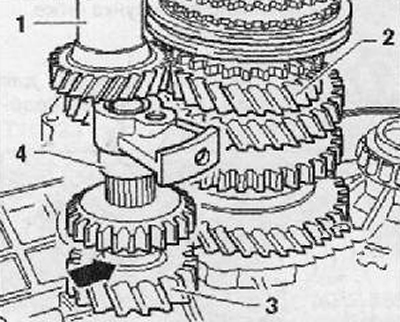
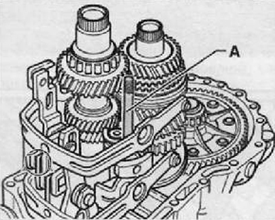
2. Insert the drive shaft (1) together with the driven shaft (2) into the clutch housing as shown in the figure below.
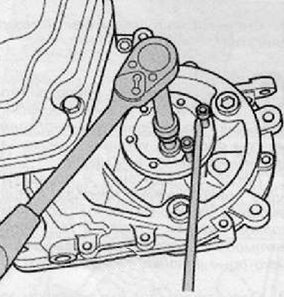
3. Tighten the fastening nuts for the input shaft bearing with the appropriate tightening torque.
4. Install reverse gear (3) onto the needle bearing on the clutch housing as shown in the figure below. Shoulder (arrow) directed away from the clutch housing.
5. Check if the reverse gear axle is complete (4) properly.
6. Insert the reverse gear shaft into the clutch housing.
7. Remove the fixing agent from all threaded holes in the reverse gear axle support; cleaning can be done with a tap.
8. Push the reverse gear axle support onto the reverse gear axle.
9. Install the shift fork to engage reverse gear (1) together with shift fork support for engaging reverse gear (2), spring (3) and slider (4), as shown in the figure below.
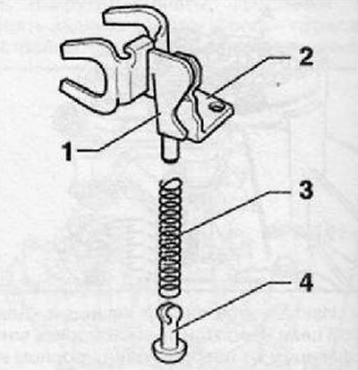
Assembly position for reverse gear
10. Tighten the mounting bolt (IN) the drive for engaging the reverse gear follows with the specified torque.
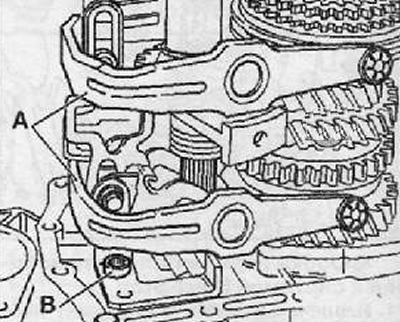
11. Install shift forks (A) together with the shift fork stems as shown in the figure below.
12. Screw in the pin (A) M8x 100 mm into the bearing of the reverse gear axle in such a way that it is aligned after the gearbox housing is installed.
13. Align the shift forks.
Note. The shift segments must fit into the grooves of the sliding clutches.
14. Apply sealant (AMV 188 200 03) evenly on the sealing surface of the clutch housing.
15. After installing the gearbox housing, tighten the fixing screws with the appropriate tightening torque.
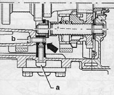
16. Screw in the reverse gear axle support screws shown in the figure below (arrow) in the following way:
Installing the screw (A), unscrew the M8x100 mm stud from the reverse gear axle support, install the screw (b) and tighten it by hand.
Tightening order:
- 1 - Screw -a- 30 Nm (М8х32)
- 2 - Wing -b- 25 Nm (М8х26)
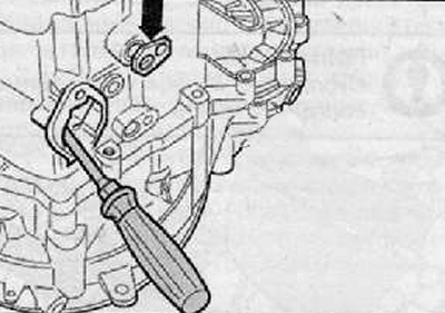
17. Install necks (arrow) shift forks as shown in the figure below. Align the gearshift drive with a screwdriver so that it is possible to install each of the journals.
18. Apply sealant (AMV 188 200 03) uniformly on the sealing surface of the lid.
19. After putting on the cover of the gearshift control shaft, tighten the screws with the application of the appropriate torque.
20. Install the shift control shaft. For this:
Set the shift forks to the neutral position.
Apply a sealant (AMV 188 200 03) uniformly on the sealing surfaces of the gearshift cover.
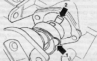
Set ledge (arrow 1) into a recess in the crankcase. Install the shift shaft so that the pin of the shift mechanism (arrow 2) entered into a fixed position in the shift forks, as shown in the figure below.
With the shift shaft cover in place, tighten the screws to the correct torque.
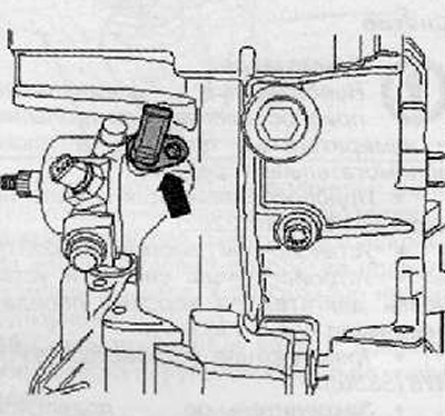
21. Gearbox for vehicles with start-stop system: By installing gearbox idle position sender -G701- (arrow), tighten the fixing screw to the specified torque as shown in the figure below.
22. Install both drive shafts with flange with springs, friction washers and conical rings as shown in the figure below.