



Contents: Controls on the left side of the…⬇ Controls on the right side of the…⬇ Controls in the center console ⬇ Interior controls and equipment…⬇ Luggage compartment equipment ⬇
The location of the controls and interior equipment on the instrument panel, center console, and driver's door is shown in Illustration 12.1. Components for which specific sections are indicated in the captions to Illustration 12.1 are described in those sections and are not discussed further.

12.1. Location of controls 1. Switch for adjusting and heating the outside rearview mirrors (see Section 9); 2. Side deflectors of the climate system (see Section 14); 3. Left steering column switch; 4. Steering wheel with horn switches, driver's front airbag (see Section 10), audio system/navigation system/phone control keys (see Section 15) and display control keys in the instrument cluster (see Section 13); 5. Instrument cluster (see Section 13); 6. Right steering column switch; 7. Central deflectors of the climate system (see Section 14); 8. Driver's seat heating switch (see Section 9); 9. Hazard warning switch; 10. Front passenger airbag status indicator (see Section 8); 11. Upper storage compartment of the instrument panel; 12. Audio/navigation system unit (see Section 15); 13. Front passenger seat heating switch (see Section 9); 14. Main storage compartment; 15. Front passenger front airbag (see Section 10); 16. Front passenger airbag switch (see Section 10); 17. Electric window lifter control switches (see Section 5); 18. Fuse box (at the end of the instrument panel, see Chapter 12); 19. Switch for external lighting devices and instrument lighting; 20. Hood release handle (see Section 3); 21. Headlight range and instrument lighting brightness controls; 22. Steering column adjustment lever (see Section 9); 23. Driver's knee airbag (see Section 10); 24. Ignition switch; 25. ASR switch (see Section 24); 26. Front and rear parking assistance switch (see Section 17); 27. Single lock key (see Section 1); 28. Transmission control lever (see Section 23); 29. Niche for small items; 30. Offroad mode switch (see Section 25); 31. Tire inflation pressure monitoring system switch (see Section 19); 32. Parking autopilot switch (see Section 17); 33. Climate control panel (see Section 14)
Controls on the left side of the instrument panel
Left steering column switch
Left steering column switch (3 in illustration 12.1) intended for:
- turn on/off direction indicators;
- switching between low and high beam headlights;
- high beam headlight alarms;
- turn on/off parking lights;
- tempostat control (if available, see Section 16).
To turn on the left or right turn signal with the ignition on, pull the left steering column stalk lever down or up, respectively (B or A in Illustration 12.2) through the point of resistance. At the same time, the indicator for the corresponding turn signals lights up in flashing mode in the instrument cluster. After completing the turn, the shift lever automatically returns to the neutral position. To force the turn signals to turn off, pull the lever back to its original position manually.
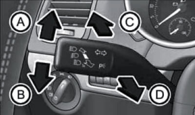
12.2. Positions of the left steering column switch
Note: Rapid blinking of the indicator indicates a malfunction of the vehicle's turn signals (no trailer!), - check the lamps.
When changing lanes, you can use the 3-fold turn signal function. Pull the upper left steering column stalk lever up or down without moving it past the point of resistance and release - the direction indicators will flash 3 times and the lever will return to the neutral position. If you do not release the lever, the direction indicators will continue to operate.
Note: This function can be turned on and off at a Skoda service station, or via the "Headlights and visibility" menu on the instrument cluster display (if this menu is available, see Section 13).
To turn on the high beam headlights with the low beam headlights on, pull the upper left steering column switch lever away from you (From the illustration 12.2). Switching on the high beam headlights is accompanied by the corresponding blue K/L light in the instrument cluster (see Section 13). To switch back to low beam mode, push it away from you again or pull the lever towards you to its original position.
To signal with high beam headlights, pull the switch lever towards you (D in Illustration 12.2). In this non-fixed position, the high beam will turn on even when the ignition is off, and will remain on until the switch is released. Switching on the high beam headlights is accompanied by the corresponding blue K/L light in the instrument cluster (see Section 13).
To turn on the parking lights (side lights on one side) turn off the ignition and move the lever up or down (A and B in Illustration 12.2).
Note: If the ignition is turned off with the direction indicators on, the parking lights will not come on. On models from 11/2010, you can turn on the parking lights on both sides by turning on the side lights and locking the car.
Right steering column switch
Note: To avoid damaging the windscreen wiper mechanism, do not operate the wipers if the glass being cleaned is dry, or move them by hand. In frosty weather, before turning on the windshield wipers for the first time during the trip, you should check whether the brushes are frozen. The windshield wipers turn on when the ignition is turned on, if they were not turned off when the ignition was turned off. In cold weather, before parking the vehicle, it is recommended to set the windshield wipers to the service or intermediate position (see below). To avoid damaging the windshield wipers, do not allow them to come into contact with gasoline or other solvents. To avoid damaging the pumps, do not use the windshield wipers when the washer fluid reservoir is empty or continuously for more than 10 seconds.
Caution: Do not leave the rain sensor on while washing your car. Before turning on the automatic windshield wiper mode in conditions where frost may form, make sure that the windshield is completely clear of frost and ice. Avoid using the automatic windshield wiper mode in dry weather, as it may mistakenly identify drops of dirt, fog or insects that have fallen on the glass as raindrops. To prevent unnecessary operation of the windshield wipers in automatic mode, replace the windshield wiper blades if they leave streaks of water or smears.
Right steering column switch (6 in illustration 12.1) designed to control windshield wipers and washing of the windshield and rear window (if available), and also headlights (with appropriate equipment). In addition, it has keys for controlling the multifunctional display of the instrument cluster (see Section 13). The lever positions are shown in Illustration 12.3. Windscreen wipers and washers operate only when the ignition is on; windscreen washer/cleaner works only when the hood is closed (if there is a hood contact switch), and washing/cleaning the rear window - only with the tailgate closed. The washer fluid supply nozzles are heated when the ignition is on.
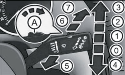
12.3. Positions of the right steering column switch for controlling the windshield wipers A. (
 ) Switch for adjusting the interval or sensitivity of the rain sensor (in mode "1"); 0. (OFF) Windscreen wipers are off; 1. (
 ) Interval or automatic mode (interval or sensitivity is adjusted by switch "A"); 2. (LOW) Turns on normal continuous operation of the windshield wipers; 3. (HIGH) Turns on the accelerated continuous operation of the windshield wipers; 4. (1x) Turns on the windshield wipers for one cycle, or, if held down, accelerates the movement of the windshield wiper blades; 5. (
 ) Turning on the supply of washer fluid and windshield wipers; 6. (
 ) Interval mode, the cleaner operates approximately every 6 seconds; 7. (
 ) Switching on the supply of washer fluid and rear window wiper
After each time the windshield wipers are switched off, and also after every third time the ignition is switched off, the windshield wiper arms stop in the alternative parking position (rise slightly from the normal parking position), to extend the life of the brushes. The windshield wipers return to their normal parking position after the engine is started.
After every second stop of the rear window cleaners, its lever stops in an alternative parking position to extend the service life of the brush (the brush "tips over"). To enable / disable this function, with the ignition on, pull the steering wheel switch to the (6 in illustration 2.3), and then turn off the ignition.
To move the wiper arms away from the windshield, they must first be set to the service position. To do this, with the hood closed, turn the ignition on and off again, and then turn on the windshield wipers for one cycle within 10 seconds (pull the switch down). If the levers were pulled away from the windshield, lower them before driving. The levers return from the service position to the park position the next time the ignition is turned on and the right steering column switch is moved again or the vehicle is moving at a speed of more than 6 km/h.
In winter, the windshield wiper levers can be set to an intermediate position (to ensure their unhindered removal from the icy glass). To do this, turn off the ignition with the windshield wipers on - they will stop in the position they were in when the ignition was turned off.
When the washer fluid supply is turned on at speeds up to 120 km/h, the windscreen wipers (front or back) turn on with a slight delay, and at speeds over 120 km/h, the windshield wipers turn on immediately. After the washer fluid supply is switched off, depending on the duration of the wash, the windscreen wipers operate 3-4 more times, and the rear window wiper - 2-3 times. At a speed of more than 2 km/h, 5 seconds after the last operation of the windscreen wipers, they operate one more time. This function of wiping off washer fluid streaks can be switched on or off at a Skoda service station.
The windshield wipers have a function of changing the operating speed depending on the vehicle speed: at a speed of less than 4 km/h, the accelerated or normal operating speed of the windshield wipers is reduced by one level. The previously selected mode is restored upon acceleration to 8 km/h.
Windshield wipers try to overcome obstacles on the glass. If the obstacle cannot be overcome within five attempts, the windshield wipers stop automatically. In this case, remove the obstruction before turning the wipers back on.
When reverse gear is engaged, the rear window wiper is automatically turned on for one cycle if the windscreen wiper is on.
At speeds over 5 km/h with windshield wipers running continuously (in normal or accelerated mode) the rear window wiper operates automatically every 30 or 10 seconds (respectively). If the rain sensor is on, the automatic rear window wiper only operates when the windscreen wipers are continuously running (the time between cycles is not maintained). Automatic operation of the rear window wiper can be enabled/disabled via the menu "Settings→Headlights and visibility→3 rear window wiper" of the instrument cluster display (if such a menu is available, see Section 13).
The car can be equipped with nozzles for supplying washer fluid to the headlights. In this case, after turning on the ignition, the first time the windshield washer is turned on, and then every fifth time the windshield washer is turned on, the headlight washer will be turned on if the low or high beam headlights are turned on, and the right steering column switch is held pulled towards the steering wheel (5 in illustration 12.3) not less than 1 second. In winter, ice should be removed from the washer fluid nozzles on the headlights using a special aerosol so that the nozzles can freely exit the bumper.
If there is a rain sensor, when the right steering column switch is moved to the position (1 in illustration 12.3) automatic windshield wiper control mode is activated. In this mode, the windshield wipers are activated when the rain sensor detects drops on the windshield. The rain sensor is built into the support of the interior rearview mirror and is glued to the windshield. The sensitivity of the rain sensor is adjusted by the switch (A): the further to the right the switch is, the higher the sensitivity, i.e. the less moisture on the glass the windshield wipers will operate.
Horn switch
The horn only works when the ignition is on.
The horn buttons are built into the steering wheel trim and are marked with corresponding pictograms (near the upper spokes of the steering wheel). Press the pad without applying significant force, since the horn switch is combined with the driver's front airbag unit.
Pedals
Models with manual transmission have three pedals (from left to right): clutch pedal, brake pedal and accelerator pad ("gas"). On models with DSG, there is no clutch pedal.
Control and free movement of the pedals should not be interfered with by foreign objects and rugs. Make sure that no loose objects are left on the floor and do not allow the transportation of loose pets. Use only mats that do not interfere with pedal control and are securely fixed to prevent slipping.
An increase in brake pedal travel indicates a leak in the brake hydraulic system.
Ignition switch
When the key is removed from the ignition switch, the steering column lock is engaged.
When the key is in the ignition switch in position ("1", see illustration 12.4), the steering column lock is not released. The ignition is off, all electrical consumers are disconnected. The key can be removed from the lock.
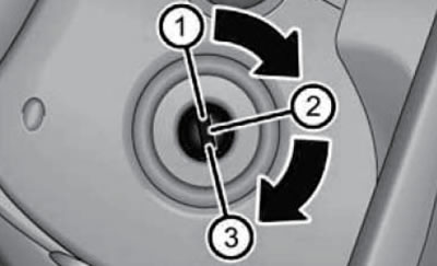
12.4. Ignition switch positions
When the key is turned to the first position ("2" in Illustration 12.4), the ignition is turned on. On diesel models, glow plugs are activated and you should wait until they are switched off before starting the engine. If the steering wheel was turned while the key was removed from the lock, when turning the key from position "1" to position "2", you should slightly turn the steering wheel from side to side to release the steering column lock.
When the key is turned all the way ("3" in Illustration 12.4), the starter is engaged and the engine starts. Powerful consumers of electricity are switched off while the starter is running. Release the key immediately after the engine starts - the key will return to position "2". Do not allow the starter to operate for more than 15 seconds. If the engine fails to start, return the key to position "1" and try again after waiting about a minute. A detailed description of the engine starting and stopping procedure is given in Section 20.
To turn off the engine, turn the key to position "1". Turn off the engine only when the vehicle is stationary. Turning off the engine while driving makes it difficult to stop the vehicle, may result in loss of control of the vehicle, and may cause serious injury. When the engine is turned off, the auxiliary brake and steering systems, the SRS system, and other safety systems do not work. Never turn the key to position "1" while the vehicle is moving.
To remove the key from the ignition on DSG models, the selector lever must be in the "P" position. If necessary, press and release the lock release button on the selector lever. If the key is left in the ignition for a long time with the engine off and the selector lever is not in the "P" position, the battery will discharge.
Headlight range control and instrument lighting brightness control
Headlight leveling regulator (21 in illustration 12.1), is designed for manual smooth adjustment of the inclination of the headlight beams under different vehicle loading conditions (see Specifications) in order to prevent oncoming drivers from being blinded by the headlights of your vehicle. Adjustment is only possible when the low beam is on. On models with xenon headlights, headlight leveling adjustment (illumination ranges) it is carried out automatically based on data from the suspension height sensor, and the regulator is not installed.
Instrument lighting brightness controller (if available) located to the left of the headlight range adjuster. On models with a multifunction instrument cluster display, the brightness of the instrument lighting is adjusted automatically. Manual adjustment is only possible if the illumination falls below the set value of the light sensor.
Outdoor Lighting Switch and Outdoor Lighting Functions
Note: Do not leave the lights on for a long time with the engine off to avoid draining the battery. Comply with legal regulations regarding the use of lighting devices. Automation of the external lighting is an auxiliary function and does not relieve the driver from the obligation to use external lighting devices properly.
Note: In cold or damp weather, the headlights may temporarily fog up on the inside due to the temperature difference between the inside and outside of the headlight. After turning on the headlights, the fogging quickly disappears, or remains for some time at the edges. Fogging may also occur on the rear combination lights. Fogging is not a sign of a malfunction and does not affect the service life of the headlights.
The switch for the exterior lighting devices and the exterior lighting function is located to the left of the steering wheel (19 in illustration 12.1). If the switch is faulty, the low beam headlights are turned on.
If the driver's door is open, the key is removed from the ignition switch and the external lighting devices are on (parking lights, side lights, low or high beam headlights), an audible signal is emitted to warn of the possibility of the battery being discharged. If you then close the driver's door, the warning signal turns off and the parking lights remain on.
In the zero position of the switch ("0") with the ignition off, the exterior lighting is off, and with the ignition on, the daytime running light (DRL) is on. To turn the DRL lighting off/on again, within 3 seconds after turning on the ignition, pull the left steering column switch towards the steering wheel and simultaneously down or up (respectively), and hold it in this position for at least 3 seconds. On models with a multifunctional display in the instrument cluster, you can also turn off/on the DRL lighting via the "Settings→Headlights and visibility" menu. Separate lamps in the fog lights are provided for the implementation of the DRL function. When the DRL is turned on, only these lamps light up (in some country variants, the rear lights and license plate lights also light up).
If there is a light sensor, there is an "AUTO" position to the right of the "0" position. In automatic mode, when the ignition is on, the "AUTO" position is illuminated, and the headlights turn on and off automatically depending on the light level (illumination is determined by a sensor in the support of the interior rear-view mirror). If the low beam headlights are automatically switched on, the "osition is additionally illuminated
 " switch. In automatic mode, the headlights turn on regardless of the light level if the speed exceeds 140 km/h for 10 seconds, and turn off if the speed does not exceed 65 km/h for two minutes. In addition, the headlights turn on automatically if the windshield wipers operate for more than 10 seconds according to the rain sensor or in continuous mode, and turn off if the windshield wipers do not operate for four minutes after that.
Note: The light sensor may not respond to rain or fog; do not stick any stickers on the windshield in front of the light sensor, so as not to disrupt the operation of the automatic system.
The side lights can be turned on regardless of the presence and position of the key in the ignition switch. To do this, turn the switch to the "position
 ". When the side lights are switched on, in addition to the corresponding lamps in the headlights and rear combination lights, the number plate light and instrument light are switched on when the ignition is switched on.
To turn on the low beam headlights manually, turn the switch to the "position with the ignition on
 ". When the low beam is on, use the left steering column switch to switch to high beam (see the relevant subsection above). If the exterior lighting switch is left in the low beam position with the ignition off, the parking lights may remain on for a while.
To turn on the fog lights (if available) pull the switch from the parking light or low beam position towards you to the first detent position. When the fog lights are switched on, the corresponding indicator in the instrument cluster comes on.
If fog lights with static cornering light function are installed, their control (switching on the corresponding fog lamp lamp) is carried out depending on the angle of rotation of the steering wheel or on the inclusion of direction indicators, subject to the following conditions:
- the engine is running and the vehicle speed does not exceed 40 km/h;
- dRL lighting not on;
- low beam headlights are turned on manually or automatically;
- fog lights not on;
- reverse gear is not engaged.
The cornering light illuminates the area around the bend before the vehicle turns. If you engage reverse gear with the cornering light function activated, both fog lights come on. In case of conflict between both options of inclusion (for example, if the steering wheel is turned to the left and the right turn signals are on), direction indicators have priority.
To turn on the rear fog light, pull the switch from the parking light or low beam position towards you until it stops. When the rear fog light is switched on, the corresponding indicator in the instrument cluster comes on. When towing a trailer connected via the original towing hitch, only the rear fog light on the trailer is switched on.
To turn off the fog lights and rear fog lights, press the switch all the way down or turn it to the "0" position.
Some models have adaptive cornering lights ("AFS"). This feature turns the headlights in the direction of the car's turn when the low beam headlights are on and the speed is over 10 km/h. The AFS function is activated/deactivated via the "Assistants" menu of the multifunction display in the instrument cluster (see Section 13). If the adaptive lighting fails, the headlights are lowered to the emergency position so as not to blind oncoming drivers.
When driving in a country where traffic is on the other side of the road, asymmetrical low beam headlights may dazzle oncoming drivers. Therefore, you should first switch the xenon headlights (via the menu "Settings→Headlights and visibility→Driving mode" of the instrument cluster display), or cover the halogen headlights with a special film of the appropriate shape. When you return to your country, switch the headlights back or remove the film from them.
Function "Coming home" allows you to light the way home after leaving the car, leaving the side lights, low beam headlights, lamps in the outside mirrors and license plate lighting on for a while (depending on equipment). To use this function, set the exterior light switch to the "AUTO" position (to have the low beam headlights on), turn off the ignition, open the driver's door, get out of the car and lock it. The headlights will turn off 10 seconds after all doors and the luggage compartment are closed. If any doors or the luggage compartment are left open, the headlights will go out 60 seconds after the ignition is turned off. Duration of the function "Coming home" can be changed via the menu of the multifunction display in the instrument cluster.
Function "Leaving home" includes side lights, low beam headlights, lamps in outside mirrors and license plate lighting (depending on the configuration) when unlocking the vehicle's main lock, when the exterior lighting switch is in the "AUTO" position and the light sensor detects darkness. The headlights turn off when the timer expires (normally - 10 seconds), either when the car is locked or when the ignition is turned on. If no door is opened within 30 seconds after unlocking, the vehicle will be automatically locked and the lighting will "Leaving home" will turn off. Duration of the function "Leaving home" can be changed via the menu of the multifunction display in the instrument cluster.
Controls on the right side of the instrument panel, on the doors and seats
The interior door trim features:
- handle for unlocking and opening the door from the inside (see Section 1);
- handrail;
- window lifter control buttons or handles (see Section 5);
- position regulator and switch for heating the outside mirrors (only in the driver's door, see Section 9);
- "SAFE" indicator for full locking of a single lock (only in the driver's door, see Section 1);
- audio system speakers;
- pocket and bottle holder;
- 1.5 l (see illustration 12.5a);
- pocket;
- a reflector or signal light that comes on when a door is opened (only in front doors, see illustration 12.5b).
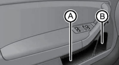
12.5a. Pocket (A) and bottle holder (B) in the driver's door
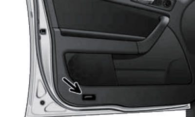
12.5b. Signal lamp in the front door
At the bottom of the outside rear-view mirrors are lamps for illuminating the area in front of the front doors. The light comes on after the door is unlocked or the luggage compartment is opened and goes out after the ignition is turned on or 30 seconds after all doors or the luggage compartment are closed. If any door or luggage compartment remains open, the light goes out within 2 minutes when the ignition is off.
The front seats have levers and/or buttons for adjusting them (see Section 9), and there may be drawers under the front seats (see illustration 12.6) for items weighing up to 1.5 kg in total. When driving, the storage boxes must be pushed under the seats until they lock. The front passenger seat may have ISOFIX mountings for child seats (see Section 8).
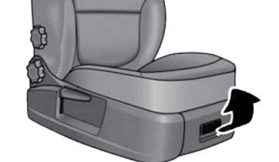
12.6. Handle of the glove compartment under the front passenger seat
A fire extinguisher can be attached to the holder under the driver's seat.
There are pockets on the rear sides of the front seat backs, and a DVD player can also be installed (see Section 15).
In the back of the rear seat in the center place there is a rear center armrest (see Section 9). The outer rear seats can be equipped with ISOFIX mountings for child seats (see Section 8).
To open the main storage compartment, press its button (see illustration 12.7a). When the glove box is open, its backlight lamp turns on. To close, pull the lid up and press it until it locks into place. The main storage compartment has a pencil holder. On some models, the glove compartment is equipped with a closable opening for the supply of cool air (from the climate system). The supply of cooled air is turned on by pulling the handle (see illustration 12.7b). When the air supply is open and the refrigeration unit is turned on, cooled air enters the glove compartment. If the air intake vent is open and the refrigeration unit is turned off, outside or unconditioned air will enter the box. If the climate control system is operating in heating mode or if cooling for the glove compartment is not required, it is recommended to close the air supply to it.
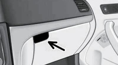
12.7a. Main storage compartment opening button
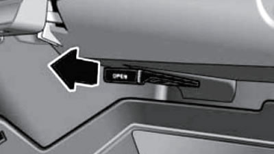
12.7b. Glove box cooling control
Caution: Do not leave the glove box open while driving, as loose items in the glove box may cause additional injury in the event of an accident.
Controls in the center console
Warning: When the vehicle is moving, do not store open containers of drinks, especially hot ones, in the holders, as during maneuvering or braking, drinks may splash and damage the vehicle's electrical equipment or cause burns.
To open the top storage compartment (11 in illustration 12.1), press his button (see illustration 12.8). When moving, the lid of the top drawer must be closed. Some models do not have a lid on the top drawer. Do not store flammable or heat-sensitive items in the top drawer (lighters, aerosols, glasses, carbonated drinks).
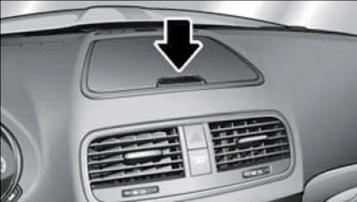
12.8. Upper storage compartment button
In the glove box (29 in illustration 12.1) mDI connector can be installed (see Section 15).
The hazard warning lights operate regardless of the presence and position of the key in the ignition switch. The hazard warning lights are switched on and off by pressing the corresponding button at the top of the central console (with a red triangle pictogram, 9 in illustration 12.1). When the hazard warning lights are on, all direction indicators and their indicators in the instrument panel, as well as the indicator in the hazard warning light switch, flash. When the hazard warning lights are switched on, they are automatically switched off while the direction indicators are on. In the event of an accident with airbag deployment, the hazard warning lights are activated automatically.
The climate control panel includes switches for heating the rear and windshields (see Section 14).
The parking brake lever is located between the seats (see Section 24), a cigarette lighter and a cup holder, in one of the slots of which an ashtray-cup can be installed. Depending on the configuration, a central front armrest can be installed (see Section 9). In this case, there are adjustable air conditioning deflectors on the rear side of the center console (see Section 14), ashtray and cup holder.
To open the ashtray on models without a center armrest, grasp it by the bottom edge (And in illustration 12.9a) and open the lid in the direction of the arrow. To remove the ashtray, grasp its fastening (B) and pull it upward. To install the ashtray, press it into the panel. The ashtray must be closed before folding the center rear seat, otherwise it may be damaged.
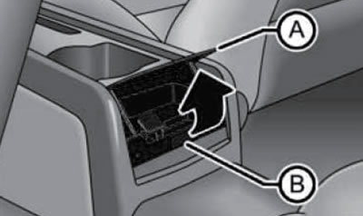
12.9a. Rear ashtray (models without central armrest)
To open the ashtray on models with a center armrest, press the bottom of the ashtray lid at (And in illustration 12.9b). To remove the ashtray, gently press the cover down until it stops and remove the insert with the cover (B). To install the ashtray, press it into the panel. The ashtray must be closed before folding the center rear seat, otherwise it can be damaged.
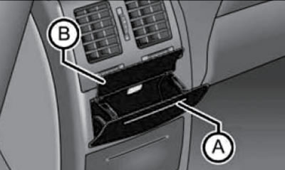
12.9b. Rear ashtray (models with central armrest)
Note: A folding storage compartment with a removable insert can be installed instead of the rear ashtray and cup holder (similar to an ashtray).
To use the cup holder in the rear of the center console, press it in the area (And in the illustration 12.10), pull it out and adjust the size by moving the bar (B). Before folding the center rear seat, the cup holder must be closed, otherwise it may be damaged.
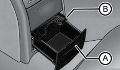
12.10. Cup holder in the rear part of the center console
To use the cigarette lighter, press it with the ignition on. As soon as the cigarette lighter coil heats up, it will return to its original position - remove the cigarette lighter from the socket and light a cigarette from the hot coil. If the cigarette lighter does not return to its original position for a long time, it should be removed from the socket and checked.
If necessary, the cigarette lighter socket can be used as a 12-volt socket. This socket, as well as the 12-volt socket in the luggage compartment, are designed to connect external power consumers with a capacity of up to 120 W.
Warning: Do not connect power sources to the socket (solar panels or chargers) for charging the car battery.
Note: Using the socket for a long time with the engine off will quickly discharge the battery. Before turning the ignition on/off, as well as before starting the engine, external electrical devices should be disconnected from the socket so that they are not damaged due to voltage surges. Unshielded devices may interfere with the vehicle's audio system and electronics.
Interior controls and equipment located on the ceiling and windshield
The windshield is equipped with a clip for parking tickets, etc. (see illustration 12.11), and also a rear view mirror (see Section 9). A light and rain sensor can be located at the base of the mirror.
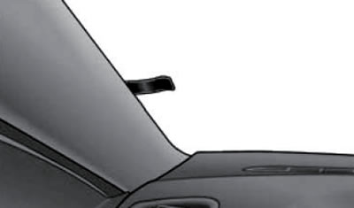
12.11. Card clip
On the ceiling, above the windshield, there are sun visors with built-in vanity mirrors and document/road map strips. To open the mirror, fold back the visor and slide the mirror cover (2 in illustration 12.12), - the backlight may turn on. The sun visor can be folded down, its edge released from the holder and moved towards the door (1). On models with double visors, after moving them to the side, the auxiliary visor can be folded towards the windscreen (3).
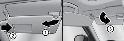
12.12. Sun visor
In the center of the ceiling above the front seats there is a ceiling console with the main cabin light and reading lights (see illustration 12.13). In addition to the lamps, the overhead console can be equipped with a switch to control the overhead hatch (see section 5), cabin volume control sensors (see Section 6), microphone (see Section 15) and a glasses case.
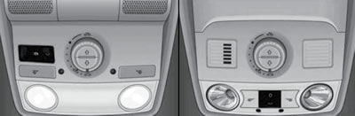
12.13. Ceiling console options
A glasses holder can be installed at the rear of the overhead console. To open it, press the button (And in illustration 12.14). When moving, keep your glasses case closed. In addition, the glasses case must be closed to ensure normal operation of the volumetric sensors of the anti-theft system.
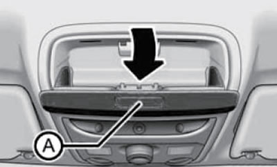
12.14. Spectacle case
A 3-position switch is used to control the front interior light. In position "0" the interior lighting is off, and in position "
 " interior lighting is on (but automatically turns off after 10 minutes to prevent battery drain). In the middle position "
 " The interior lighting turns on when the vehicle is unlocked, any door is opened, or the key is removed from the ignition, and turns off 30 seconds after all doors are closed, when the ignition is turned on, or when the vehicle is locked. This only applies if the switch corresponding to the lamp is in the position for switching on via the door contact switches. If the door is left open, the interior body lighting is switched off for 10 minutes to prevent the battery from discharging.
In some configurations (except for models with interior volume sensors) the front interior light has two built-in lamps that illuminate the transmission control lever and the center console. These lamps turn on automatically after the parking lights are turned on.
The front reading lights are switched on/off using individual buttons located next to them.
Rear reading lights are located above the rear door openings (see illustration 12.15), their diffusers are combined with 3-position switches (similar to the front interior light switch, see above).
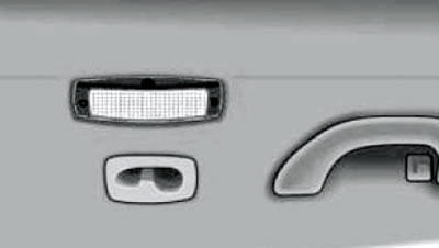
12.15. Rear reading light
There are handrails above the doorways. There are hooks for clothes in the rear grab handles and on the B-pillars of the body. The maximum load on the hooks is 2 kg.
Note: Clothes hanging on hooks must not obstruct the driver's view; there should be no heavy or sharp objects in your pockets.
The rear part of the ceiling is where the seat belt for the center rear seat is attached (see Section 7).
Luggage compartment equipment
In some trim levels, a CD changer may be installed in the left side trim of the luggage compartment (see illustration 15.2). The luggage compartment lighting is switched on after opening the tailgate. If the tailgate remains open, the light goes out after 10 minutes.
To increase the volume of the luggage compartment, you can fold the rear seat backs individually, fold the rear seats or remove them (see Section 9). Some models have a removable bag for transporting up to two pairs of skis with a total weight of up to 10 kg. To load the skis, open the rear doors, fold down the back of the central rear seat (see Section 9) and place the empty bag in the space between the front and rear seats so that the end with the zipper lies in the luggage compartment. Then open the luggage compartment, place the skis in the bag with the front ends facing backwards and close it with a zip. To secure the skis, take the strap with two fasteners out of the bag pocket (And in illustration 12.16), insert them into the locks (C) of the central safety belt, place the belt in the center of the skis between the back and the tip of the binding and tighten it tightly by pulling the free end (B). After using the bag, it should be dried.
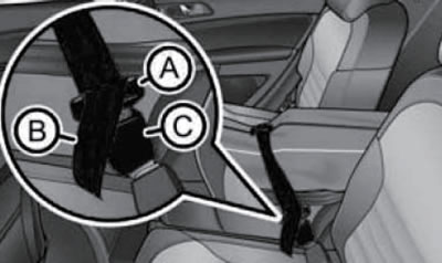
12.16. Securing skis in a removable bag
The side trim of the luggage compartment may contain: a 12-volt socket (on the right side, see the subsection "Controls on the center console" above), a lamp (on the left side), fold-out hook for shopping bags, rails with sliding hooks, strap, fastening loops and compartments for storing various things.
Removable storage compartment on the left side (And in the illustration 12.17) is designed for small items weighing up to 1.5 kg, and the storage compartment on the right (B) is designed for small items weighing up to 0.5 kg.
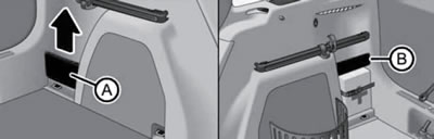
12.17. Storage boxes on the side trim of the luggage compartment
On the right luggage compartment trim by means of a flexible insert (see illustration 12.18) you can organize a storage compartment for items weighing up to 8 kg. To remove the flexible insert, grab its corners, press them towards each other, slide it up and separate it from the wall. To install, insert both ends into the holes in the trim and slide the insert down.
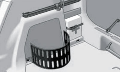
12.18. Flexible insert
There are loops and clamps for fastening on the side walls of the luggage compartment (left side of illustration 12.19), or loops for fastening and a fastening rod (right side). The fastening loops and clamps or the loops and fastening bar with hooks can also be used to install fixing nets for storing small pieces of luggage. Instructions for using the securing nets are included with these nets.
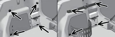
12.19. Hinges and clamps for fastening/fastening points and fastening plate
On the side walls of the luggage compartment there are fastening rods with two sliding hooks for hanging small luggage (see illustration 12.20), for example, bags, etc. Each hook can hold a load weighing up to 7.5 kg. To move the hook to a different position, fold it up in the direction of the arrow (1) so that it is at an angle of approximately 45°, slide the hook to the desired position in the direction of the arrow (2) and fold it down in the direction of the arrow (3) until it stops. To remove the hook from the fastening bar, fold it up in the direction of the arrow (4) until it is released. To install the hook on the mounting rod, place it in a vertical position in the direction of the arrow (5), press it lightly and fold the hook down as far as it will go against the direction of the arrow (4) until it clicks into the locked position.
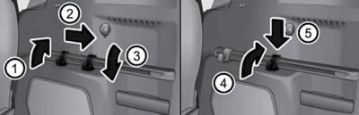
12.20. Fastening strips with sliding hooks/removing hooks
Examples of securing the restraining fixing net as a transverse pocket, floor net and longitudinal pocket are shown in Illustration 12.21. The strength of the net allows items with a total weight of up to 3.5 kg to be placed in the pocket. Heavier items are not secured sufficiently, which may result in the risk of injury and damage to the net. Do not place objects with sharp edges in the nets, as this may damage the net.
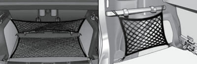
12.21. Fixing net: transverse pocket and floor fixing net (left) or longitudinal pocket (right)
The contents of the luggage compartment are covered by a rear shelf. When the safety cords are fastened, the rear shelf rises and falls together with the tailgate. You can place light items of clothing on the shelf that do not obstruct your view. Do not allow objects lying on the luggage compartment shelf to rub against the rear side windows or the rear door glass, otherwise the antennas or heating elements of the rear door glass may be damaged. To remove the shelf (for example, for transporting high luggage) unhook its restraining cords from the tailgate (1 in illustration 12.22), and then pull the shelf out of the side fasteners (2). The removed shelf can be installed behind the rear seat backs. The shelf is installed in reverse order.
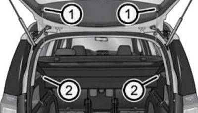
12.22. Luggage compartment shelf mounting points
Dividing network
Dividing network (additional equipment) can be installed behind the rear or front seats (see illustration 12.23). To install the separator net, remove the luggage compartment shelf (see above), take the separator net out of the cover and unfold both arms of the spacer bar until they enter the fixed position with a characteristic sound. Then insert the crossbar into the grip (B) on one side, pull the bar forward and insert the other end of the bar into the grip on the opposite side in the same way. Attach the snap hooks (C) at the ends of the tether strap to the anchorage eyes behind the rear seats or to the anchorage tabs behind the front seats and thread the strap alternately through the fasteners on both sides. On models with a transformable floor, the lower fastening tabs on the support skids should be used to enter the carabiners into a fixed position. The opening (D) in the dividing net is used to thread the seat belt. To remove the net, release the harness straps on both sides, release the carabiners (C) from the clamps, and then move the spacer bar back on both sides one by one and remove it from the fastenings (B). To fold the net, press the red button on the hinge (A) - it will be released. Place the folded partition net into the cover, close it and attach the cover with plastic carabiners to the loops on the left or right wall of the luggage compartment.
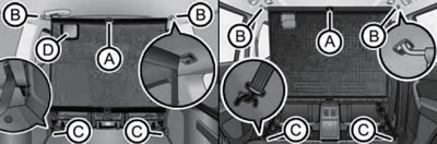
12.23. Installing a separation net behind the rear (left) or front (right) seats
Luggage compartment floor
Depending on the presence of a spare wheel, there are 3 options for the luggage compartment floor.
Basic version - with tire repair kit (tire first aid kit), without spare tire (the floor is 182 mm below the loading edge, and after folding or removing the rear seats, a level floor is created).
Intermediate option - with tire repair kit, without spare wheel (the floor is located at a level of 34 mm below the loading edge and covers the next cargo compartment with a volume of 61 liters and a height of about 13 cm). After folding the backrests of the rear seats, a step of 5 cm in height is formed, and after folding or removing the rear seats, a step of 15 cm in height is formed. If you remove the floor in the intermediate version, then after folding or removing the rear seats, a flat floor is formed.
Raised floor level - for placement of spare wheel, without tyre repair kit (the floor is 25 mm below the loading edge, and on the sides in the recesses of the upholstery there are small compartments with a total volume of about 8 liters). After folding the rear seat backs, a 3 cm high step is created. After folding or removing the rear seats, a 15 cm high step is created. It is not possible to obtain a flat luggage compartment floor with this option. Boxes behind the wings (right and left) are formed by themselves when the floor panel is removed.
The maximum specific load on the floor surface is 75 kg.
To remove the floor on models without a spare wheel, fold it in the direction of the arrow (1 in illustration 12.24), fold it in the direction of the arrow (2), pull the locking levers on both sides in the direction of the arrow (3) and remove the floor upwards in the direction of the arrow (4). Installation is carried out in the reverse order, making sure that the support rails are correctly fastened. To fix the floor (on models without spare wheel) in the folded position, fold up the hooks on the mounting strip (1 in illustration 12.20), fold the floor up from the back, fold the hooks down as far as they will go (3) and rest the floor on them. To remove the support rails (on models without spare wheel), release the stoppers with a flat screwdriver (In the illustration 12.25) and, holding the rack (A) alternately at points (1 and 2), pull it in the direction of the arrows. Installation is carried out in reverse order.
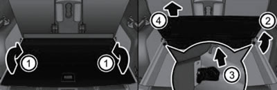
12.24. Removing the luggage compartment floor (without spare tire)
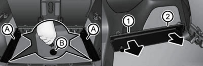
12.25. Removing the floor support rails (without spare tire)
The floor sides on models with a spare wheel can be folded towards the centre to provide space for bags (see illustration 12.26). The floor on models with a spare wheel can be locked in the folded position in the same way as the floor on models without a spare wheel.
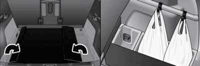
12.26. Folding down the sides and fastening the bags (models with spare wheel)
Depending on the configuration, a spare wheel, on-board tool kit or tire repair kit can be stored under the floor (see Introduction). In addition, the luggage compartment has storage space for an emergency stop sign and a first aid kit (see illustration 12.27). On models with a spare tire, the warning triangle can be stored in the tray to the right of the spare tire.
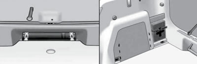
12.27. Storage locations for the emergency stop sign (left) and first aid kit (right)