



Removal
Note: Do not remove the fuel injectors until the engine has cooled down.
1. Remove the intake manifold assembly (for more details, see the relevant section in the chapter "Intake and exhaust system").
2. Remove the fuel rail assembly (for more details, see the relevant section in this chapter).
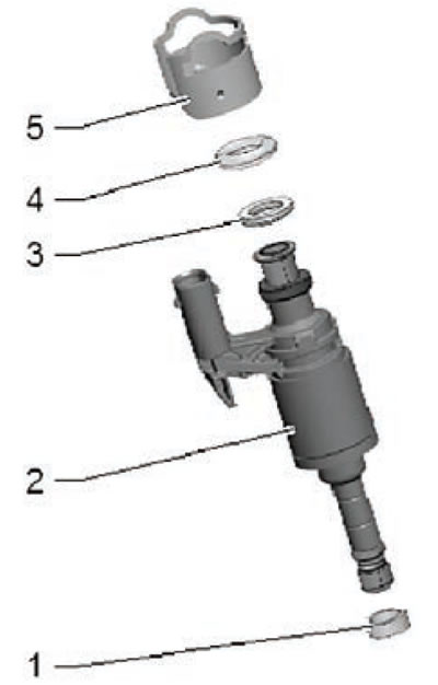
3. Remove the sealing ring (4) from the fuel injector (2) as shown in the figure below.
4. Disconnect the wiring harness connectors from the fuel injectors.
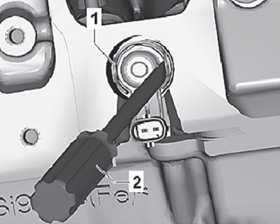
5. Using a screwdriver (2), lift and remove the covers (1) shown in the figure below.
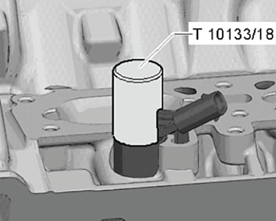
6. Press the special sleeve (T10133/18) onto the fuel injector, as shown in the figure below.
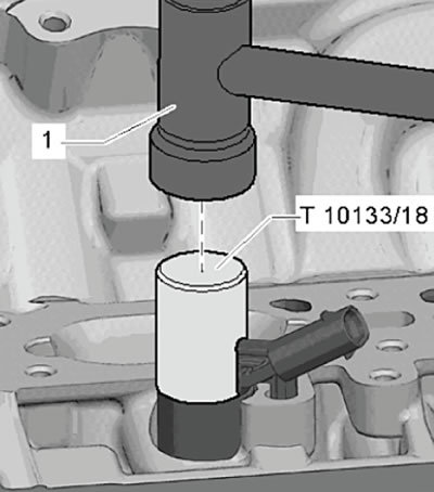
7. Carefully tap the special bushing several times with a hammer to release the fuel injector, as shown in the figure below.
Note:
- Use a torque wrench to remove the fuel injector.
- Set the torque limit on the torque wrench to 5 Nm.
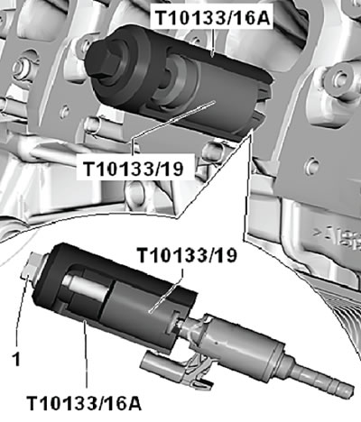
8. Install the special puller (T10133/19) into the recess on the fuel injector, as shown in the figure below.
9. Install a special device on the puller (T10133/16A), as shown in the figure below.
10. Tighten the bolt (1) to press out the fuel injector from the cylinder head.
11. If the 5 Nm limit is not enough to press the fuel injector out of the cylinder head. It is necessary to repeat the operation described above using a special device (T10133/18).
12. Repeat the removal operations for each injector.
Note:
- If the pressing conditions are not met (given moment) fuel injectors, they may be damaged.
- Always replace the combustion chamber sealing rings after removing the fuel injectors.
13. Remove the intake manifold gasket assembly.
Disassembling the injector
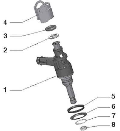
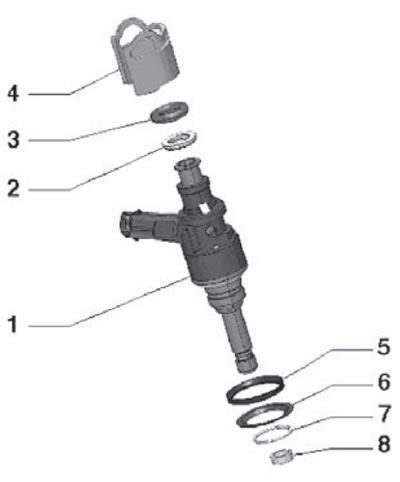
1. Pull and remove the support ring (4) and spacer ring (2) from the fuel injector (1) as shown in the figure below.
2. Remove the retaining ring (7) and the upper sealing disc (5), then remove the lower sealing disc (6), as shown in the figure below.
3. Carefully remove the combustion chamber sealing ring (8). To do this, use a suitable knife to carefully cut the ring and remove it from the injector.
Note: Check and ensure that the sample on the fuel injector is not damaged. If any damage to the sample is detected, the fuel injector must be replaced.
Assembling and installing the injector
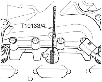
1. Using a special nylon brush, clean the holes in the cylinder head for installing the fuel injectors, as shown in the figure below.
Note:
- Always replace the sealing ring and combustion chamber ring after disassembly.
- Replace the fuel injector spacer ring if it is damaged.
2. If the fuel injector is to be reused, it is necessary to remove any carbon deposits from the area where the combustion chamber ring is installed using a clean rag.
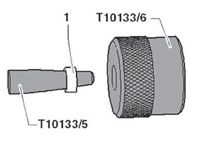
3. Install the special tool (T10133/5) together with the new combustion chamber ring (1) onto the fuel injector (2) as shown in the figure below.
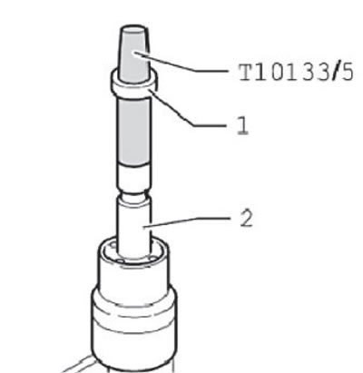
4. Place the combustion chamber sealing ring on the mounting cone (T10133/5) and move it using the special sleeve (T10133/6) as far as possible along the cone, as shown in the figure below.
5. Turn the bushing assembly (T10133/6), move it and install the combustion chamber sealing ring into the recess, as shown in the figure below.
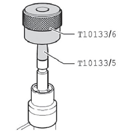
Note: When installing the combustion chamber seal ring onto the fuel injector, the ring expands.
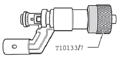
6. Press on the calibration mandrel (T10133/7), carefully turning it (within half a turn), until it stops on the fuel injector, as shown in the figure below.
7. Turn the calibration mandrel (T10133/7) in the opposite direction.
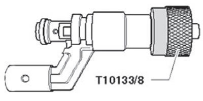
8. Press on the calibration mandrel (T10133/8), carefully turning it (within half a turn), until it stops on the fuel injector, as shown in the figure below.
9. Turn the calibration mandrel (T10133/8) in the opposite direction.
10. Install the support ring (4) and spacer ring (2) onto the fuel injector (1) as shown in the figure below.
11. Before installing the fuel injector (1), apply fresh engine oil to the new sealing ring (3).
Note: Do not apply engine oil to the combustion chamber seal ring.
12. Install and press the fuel injector into the hole in the cylinder head until it stops (there should be no oil or other flammable or lubricating materials on the cylinder head or in the hole for installing the fuel injector). Be extremely careful when installing the fuel injector into the cylinder head to ensure the injectors are seated properly.
Note:
- The nozzle should be installed without difficulty and without applying much force. If necessary, wait until the thickness of the combustion chamber ring decreases under pressure and takes the shape of a sample.
- Be extremely careful about the correct installation of the fuel injectors in the cylinder head.
Note: The fuel injector electrical connector terminals must be installed in the cylinder head recesses.
13. Install the fuel rail assembly (for more details, see the relevant section in this chapter).
14. Install the intake manifold assembly (for more details, see the relevant section in the chapter "Intake and exhaust system").
15. Connect a special scanning equipment to the diagnostic connector and clear the fuel injector initialization errors.
16. Turn off the ignition.